Turbine blade

a turbine blade and blade technology, applied in the field of turbine blades, can solve the problems of inability to economically achieve subsequent welding and/or brazing, and difficulty in maintaining the separation of passages in the core,

Inactive Publication Date: 2015-06-09
ANSALDO ENERGIA IP UK LTD
View PDF37 Cites 22 Cited by
  • Summary
  • Abstract
  • Description
  • Claims
  • Application Information

AI Technical Summary

Benefits of technology

[0015]An advantageous embodiment of the turbine blade is characterized by the fact that the slots are machined in a thickened portion of the root area. That is, there is material added to the lower part of the root of the turbine blade. After the material has been added, the slot is machined into the added material to accommodate the plate. This is advantageous because the load bearing flanks of the root of the turbine blade are not affected by the slots and stress concentration caused by the machining of the slots is avoided. The covering plate can then be slideably introduced in the slot to sealingly cover the respective hole. If necessary, this plate can be removed by simply sliding it back. Thus, maintenance work of the root of the turbine blade and the cooling passages can be easily conducted.
[0016]Another advantageous embodiment of the turbine blade is characterized by the fact that the plate is removably secured by the flanks of the rotor of the axial turbine. This is an easy, fail-safe and cost effective way for securing the plate against movement. A typical application could be, for example, the low pressure turbine stage of a gas turbine, particularly a stationary gas turbine.
[0023]This process can be very advantageous if used for refitting existing turbine blades, since the material structure of the existing blade is not affected by the assembly of the plate.

Problems solved by technology

During the process of casting the internal passages it is often difficult to maintain the separation of the passages in the cores due to thermal strains caused by differential heating and cooling rates of the core and surrounding metal.
Once applied to the turbine blade, subsequent welding and / or brazing is not feasible in an economical way.

Method used


Image

  • Turbine blade
  • Turbine blade
  • Turbine blade

Examples


Embodiment Construction

[0030]Referring now to the drawings, wherein like reference numerals designate identical or corresponding parts throughout the several views. The drawings are for explanatory purposes only.

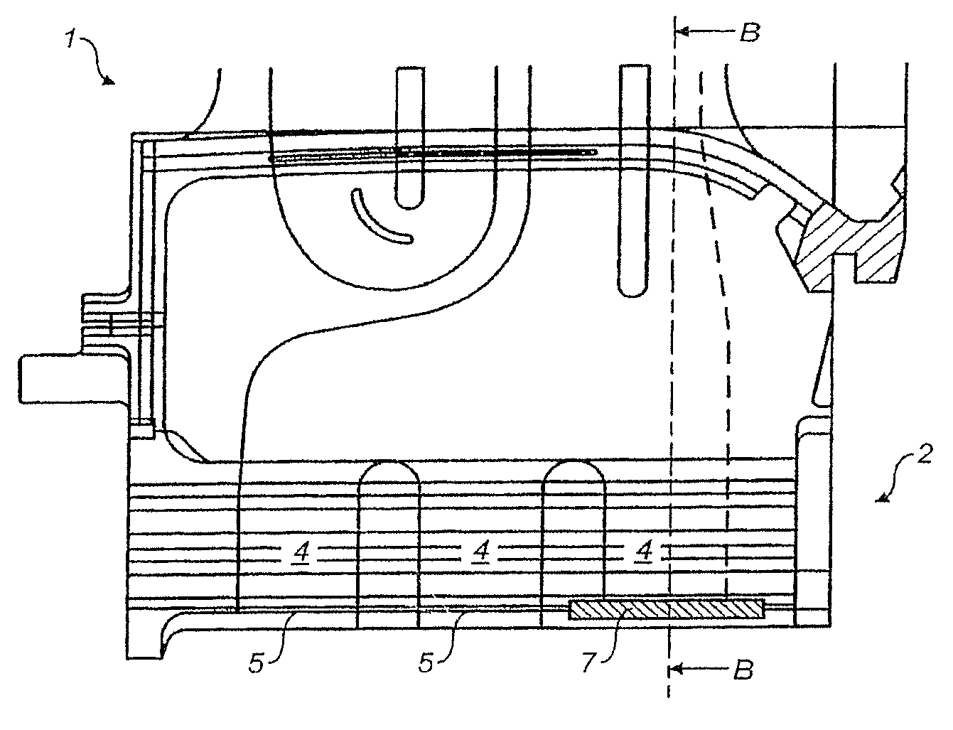
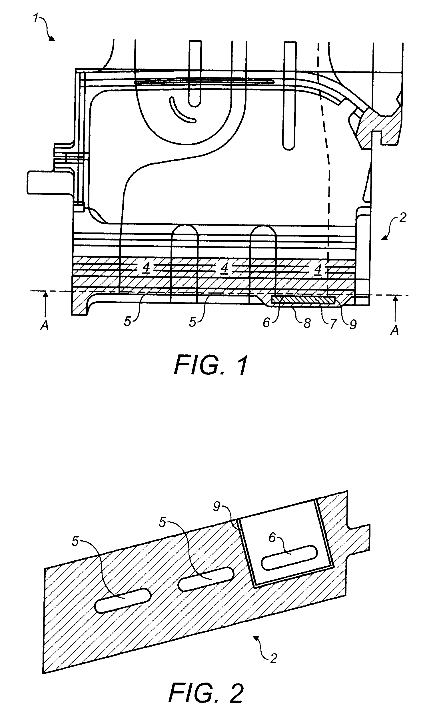
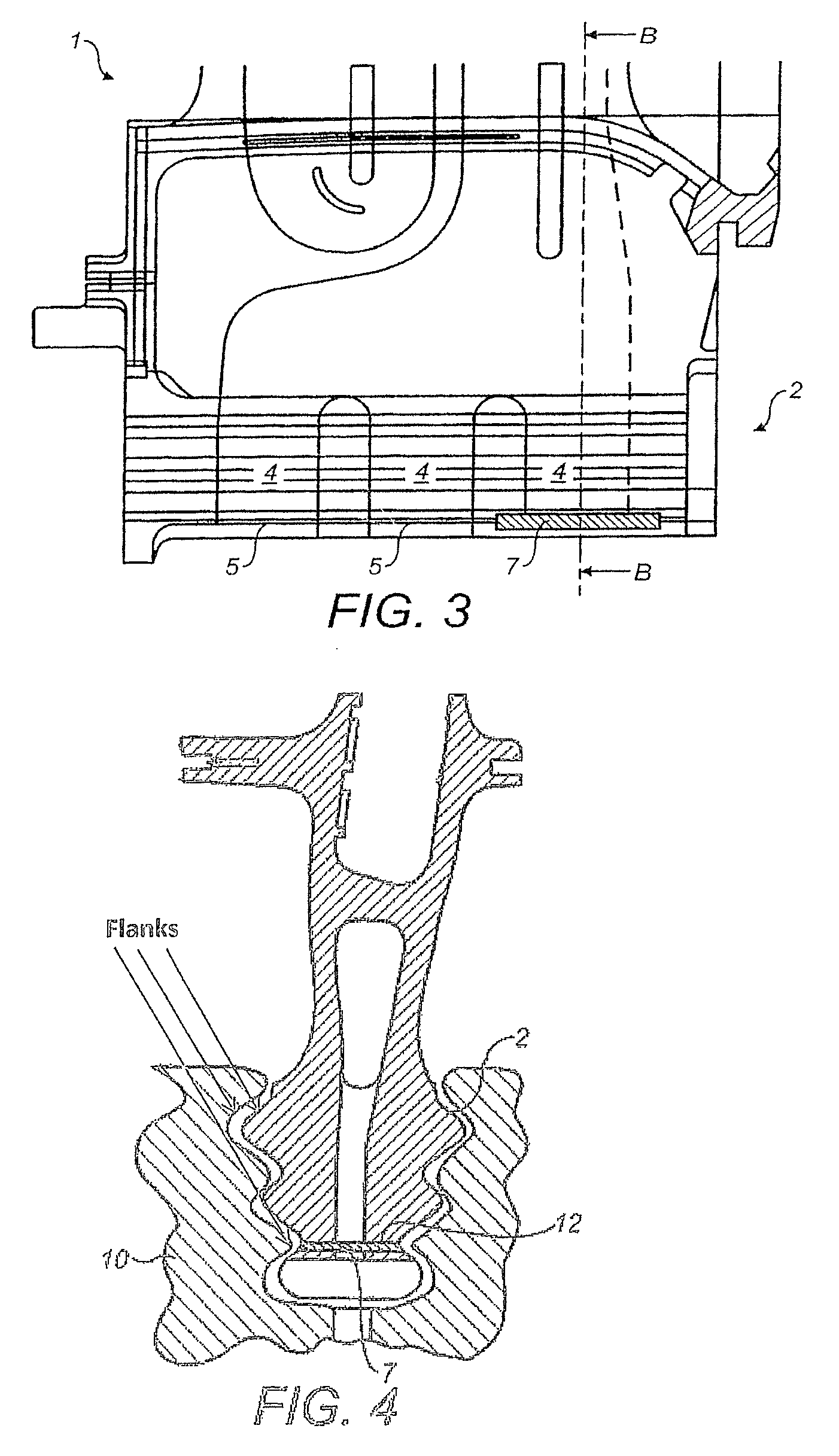
[0031]FIG. 1 shows partial spanwise cross-section of a turbine blade 1 of a gas turbine according to principles of the present invention. It extends from the root section 2 to the tip (not shown) and includes several internal passages 4. Further, FIG. 2 shows a cross sectional view of the turbine blade 1 along line A-A of FIG. 1. A passage 4 extends from the supply hole 5 for cooling air at the root 2 radially outward to the tip. Cooling air can exit through cooling slots (not shown). The hole 6 at the root 2 is closed off by a cover plate 7, which is removably secured to the root 2 of the turbine blade 1 by insertion into a slot 9 machined into added material at the root 2 of the blade 1. The slot 9 is furnished as a blind slot 9, as can be seen from FIG. 2, where the area of the blind slot 9 is ...


PUM

PropertyMeasurementUnit
thicknessaaaaaaaaaa
thicknessaaaaaaaaaa
heat resistingaaaaaaaaaa

Abstract

A turbine blade of an axial turbine includes internal cooling fluid passages with radially outwardly extending passages connected to holes in the blade root. The holes are generally core printouts providing stability to the core during the casting process, but are not needed and need to be closed to guarantee the functioning of the cooling system. This is achieved by at least one covering plate. The plate is held by at least two slots located at the root of the turbine blade. Thus, the supply holes for cooling fluid located at the root section are closed by a simple mechanical device, e.g., a plate that does not require any subsequent brazing / welding operations. In addition, the plate is removable to facilitate inspection / cleaning, or further processing of the blade at service intervals.

Description

[0001]This application claims priority under 35 U.S.C. §119 to Swiss App. No. 02179 / 10, filed 27 Dec. 2010, the entirety of which is incorporated by reference herein.BACKGROUND[0002]1. Field of Endeavor[0003]This invention relates to a turbine blade, and further relates to a process for producing a turbine blade.[0004]2. Brief Description of the Related Art[0005]Turbine blades are subjected to very high temperatures of the hot fluid driving the turbine. In order to prevent damage to the blades due to the high temperatures and in order to assure a reasonable lifetime of the turbine, turbine blades are often cooled externally and internally by a cooling medium, typically by using cooling air bled from the compressor of the gas turbine. Internal cooling of the turbine blade is realized by several passages within the blade between the pressure sidewall and the suction sidewall of the turbine blade. The passages typically extend spanwise from the root of the blade to its tip. Some of the...

Claims


Application Information

Patent Timeline
Patent Type & Authority Patents(United States)
IPC IPC(8): F01D5/08F01D5/18
CPCF01D5/081F01D5/087F01D5/188Y10T29/49341
Inventor WARDLE, BRIAN KENNETHDIDION, CHRISTOPHBRANDL, HERBERTNAIK, SHAILENDRA
Owner ANSALDO ENERGIA IP UK LTD
Why Eureka
Try Eureka