Suction cleaner and operation method thereof

a technology of suction cleaner and operation method, which is applied in the direction of suction cleaner, cleaning process and apparatus, chemistry apparatus and process, etc., can solve the problems of less dust collection capacity low efficiency of handheld suction cleaner, and inability to intelligently function of conventional handheld suction cleaner

a technology of suction cleaner and operation method, which is applied in the direction of suction cleaner, cleaning process and apparatus, chemistry apparatus and process, etc., can solve the problems of less dust collection capacity low efficiency of handheld suction cleaner, and inability to intelligently function of conventional handheld suction cleaner

US9055848B2Active Publication Date: 2015-06-16IND TECH RES INST

Image

  • Suction cleaner and operation method thereof
  • Suction cleaner and operation method thereof
  • Suction cleaner and operation method thereof

Examples


Embodiment Construction

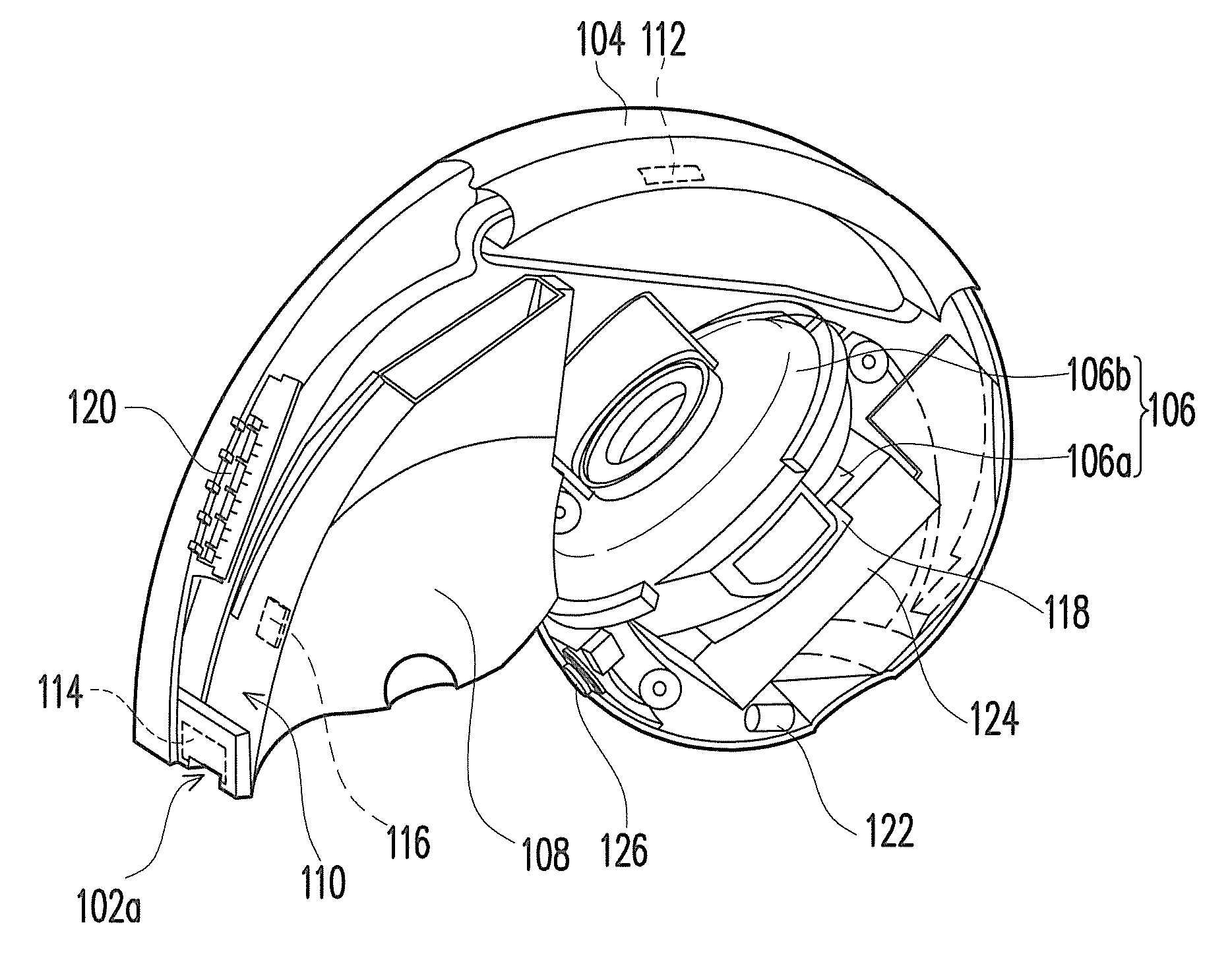
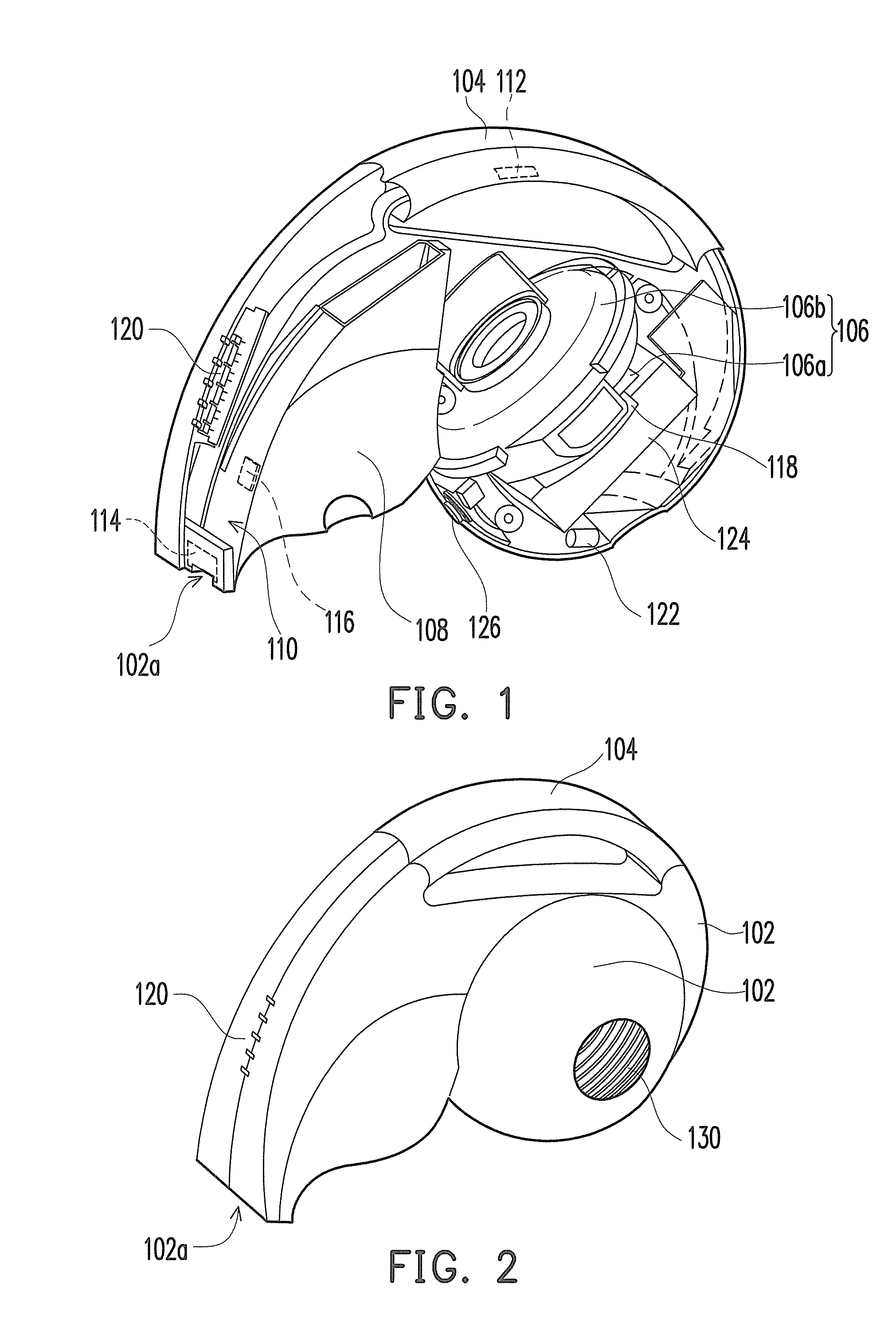
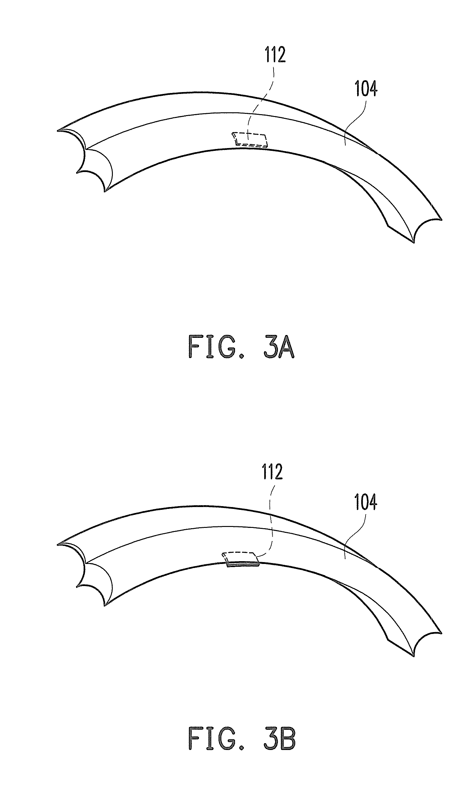
[0016]FIG. 1 is a schematic perspective view illustrating a suction cleaner according to this exemplary embodiment of the disclosure. FIG. 2 is a schematic view illustrating the exterior design of the suction cleaner according to this exemplary embodiment of the disclosure. With reference to FIG. 1 and FIG. 2, the suction cleaner of this exemplary embodiment includes a housing 102, a holding part 104, an impeller module 106, a dust-collecting container 108, a first sensing device 112, a second sensing device 114, a third sensing device 116, and a controller 118.

[0017]An end of the housing 102 has a dust-suction opening 102a through which dust particles or debris can be sucked into the suction cleaner. In this exemplary embodiment, the housing 102 can further includes an air outlet 130 for dissipating heat and circulating air within the suction cleaner.

[0018]The holding part 104 is connected to the housing 102. The embellished exterior of the suction cleaner is constituted by the hou...


PUM


Abstract

A suction cleaner and an operation method thereof are provided. The suction cleaner includes a housing, a holding part, an impeller module, at least one sensing device, and a controller. An end of the housing has a dust-suction opening. The impeller module is located inside the housing, and a channel is located between the impeller module and the dust-suction opening. The controller is electrically connected to the sensing device to drive and adjust the rotation rate and the suction force of the impeller module, and thus the power consumption of the suction cleaner can be reduced.

Description

CROSS-REFERENCE TO RELATED APPLICATION[0001]This application claims the priority benefits of U.S. provisional application Ser. No. 61 / 411,932, filed on Nov. 10, 2010 and Taiwan application serial no. 100114113, filed on Apr. 22, 2011. The entirety of each of the above-mentioned patent applications is hereby incorporated by reference herein and made a part of this specification.TECHNICAL FIELD[0002]The disclosure relates to a suction cleaner and an operation method thereof. More particularly, the disclosure relates to a handheld suction cleaner and an operation method thereof.BACKGROUND[0003]A handheld suction cleaner is compact, cordless, and thus applicable to vehicles or in other places where no power jack is configured. However, the handheld suction cleaner is powered by a rechargeable battery, and the running time of the charged handheld suction cleaner soon begins to decline. In most cases, a conventional handheld suction cleaner can merely work for approximately ten minutes or...

Claims


Application Information

Patent Timeline
16 Jun 2015
Publication
US9055848B2
IPC
A47L9/28; A47L5/24
CPC
A47L5/24; A47L9/281; A47L9/2842; A47L9/2857
Inventors
LIU, CHUN-HSIEN; TSAI, YA-HUI