
Bicycle shock assemblies with plunger operated valve arrangement

a technology of plunger and valve arrangement, which is applied in the field of bicycle shock assemblies, can solve the problems of progressively stiffer shock, limited suspension as well as bicycle structure, etc., and achieve the effect of altering the shock performan

Active Publication Date: 2015-06-16
TREK BICYCLE CORPORATION
View PDF50 Cites 6 Cited by
  • Summary
  • Abstract
  • Description
  • Claims
  • Application Information

AI Technical Summary

Benefits of technology

This design enhances shock performance by maintaining responsiveness and comfort across a broader range of displacements, reducing stiffness and improving rider control on uneven terrain without increasing shock length.

Problems solved by technology

Although such discontinuities are generally negligible for cyclists operating on paved surfaces, riders venturing from the beaten path frequently encounter such terrain.
Even though suspension features have proliferated in bicycle constructions, the performance of the suspension as well as the structure of the bicycle are often limited to or must be tailored to cooperate with the structure and operation of the shock.
That is, the compressibility of the gas contained in the shock results in the shock feeling progressively stiffer as the overall shock length continues to shorten.

Method used


Image

  • Bicycle shock assemblies with plunger operated valve arrangement
  • Bicycle shock assemblies with plunger operated valve arrangement
  • Bicycle shock assemblies with plunger operated valve arrangement

Examples


Embodiment Construction

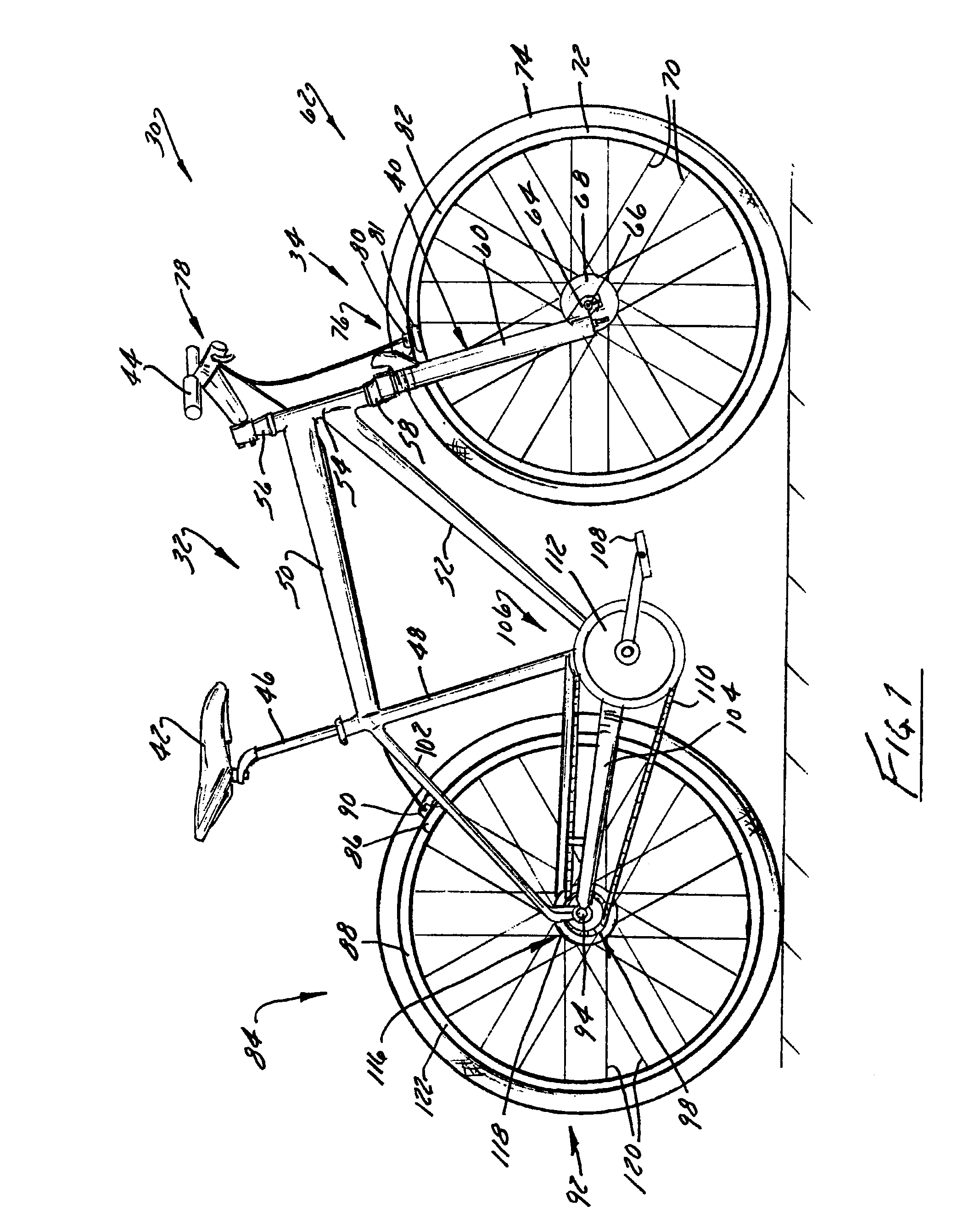
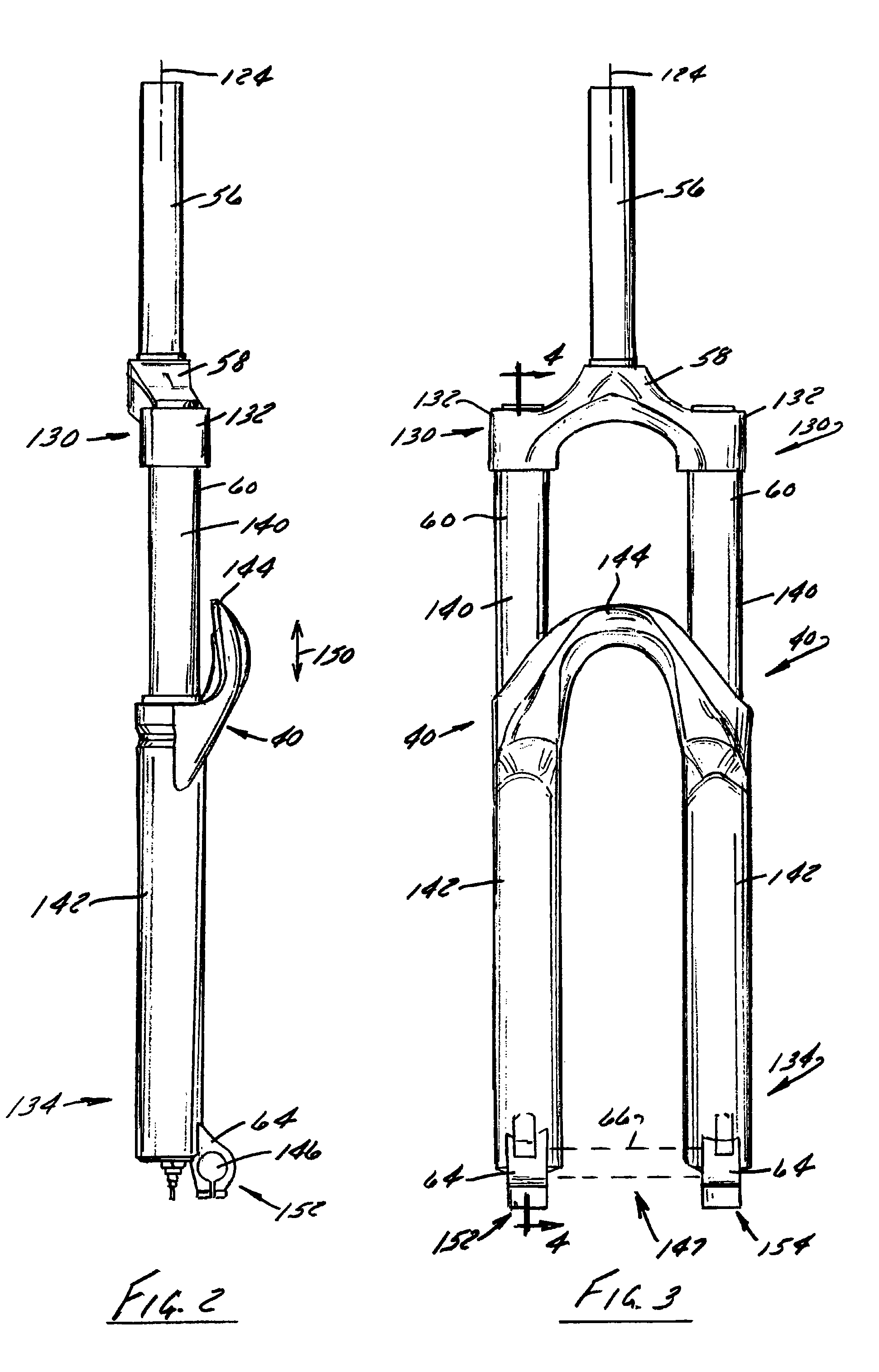
[0042]FIG. 1 shows a bicycle 30 having a frame assembly 32 equipped with at least one suspension system 34 that includes a shock absorber, shock assembly, or shock 40 that is constructed according to at least one of the embodiments of the present invention according to the present invention. Bicycle 30 includes a seat 42 and handlebars 44 that are attached to frame assembly 32. A seat post 46 is connected to seat 42 and slidably engages a seat tube 48 of frame assembly 32. A top tube 50 and a down tube 52 extend in a forward direction relative to seat tube 48 to a head tube 54 of frame assembly 32. Handlebars 44 are connected to a stem 56 that passes through head tube 54 and engages a fork crown 58. A pair of forks 60 extend from generally opposite ends of fork crown 58 and support a front wheel assembly 62 at an end of each fork or a fork tip 64. Fork tips 64 engage generally opposite sides of an axle 66 that cooperates with a hub 68 of front wheel assembly 62. A number of spokes 7...


PUM


Abstract

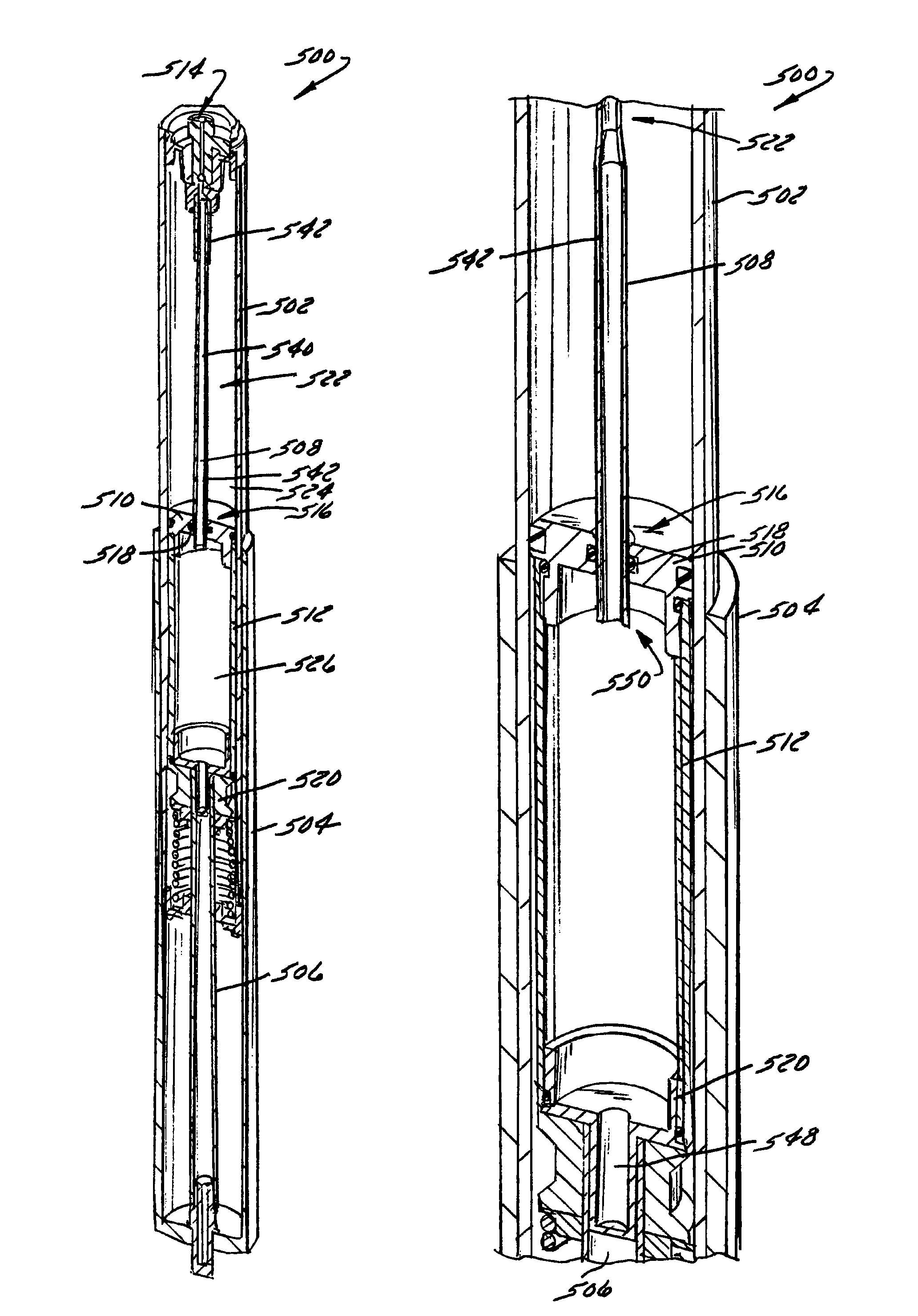
A shock absorber, which is particularly applicable to bicycles, includes a secondary chamber whose volume selectively contributes to a volume associated with a primary chamber of the shock. A piston is supported by a compression rod and cooperates with a shock tube to define the primary chamber. The secondary chamber is fluidly isolated from the primary chamber by a valve arrangement positioned proximate the piston. A plunger extends along a longitudinal length of the shock and forms or interacts with the valve arrangement such that the secondary chamber is selectively fluidly connected to the primary chamber so the primary and secondary chambers of the shock assembly contribute to the performance of the shock for a selected portion of shock travel.

Description

BACKGROUND OF THE INVENTION[0001]The present invention relates generally to bicycles and, more particularly, to shock assemblies that are constructed to facilitate controlled movement between movable members of a bicycle, such as a frame and a wheel assembly.[0002]The primary structural component of a conventional two-wheel bicycle is the frame. On a conventional road bicycle, the frame is typically constructed from a set of tubular members assembled together to form the frame. For many bicycles, the frame is constructed from members commonly referred to as the top tube, down tube, seat tube, seat stays and chain stays, and those members are joined together at intersections commonly referred to as the head tube, seat post, bottom bracket and rear dropout. The top tube usually extends from the head tube rearward to the seat tube. The head tube, sometimes referred to as the neck, is a short tubular structural member at the upper forward portion of the bicycle which supports the handle...

Claims


Application Information

Patent Timeline
Patent Type & Authority Patents(United States)
IPC IPC(8): F16F9/48B62K25/08F16F9/02B62K25/04
CPCB62K25/08F16F9/486F16F9/0236B60G2202/242B62K2025/048B60G2300/12F16F9/0218F16F9/48
Inventor GONZALEZ, JOSE L.BUHL, GREGORY PAUL
Owner TREK BICYCLE CORPORATION
Learn More