Gas-discharge lamp

a technology of gas discharge lamp and discharge lamp, which is applied in the direction of fixed installation, transportation and packaging, lighting and heating equipment, etc., can solve the problems of substantial light loss, effective waste, and light fraction, and achieve the effect of increasing the width of the arc, increasing the light intensity, and increasing the light outpu

Inactive Publication Date: 2015-06-16
LUMILEDS
View PDF15 Cites 0 Cited by
  • Summary
  • Abstract
  • Description
  • Claims
  • Application Information

AI Technical Summary

Benefits of technology

[0008]The narrower vertical stripe has a number of positive effects. For example, because the narrower vertical stripe blocks less light, the influence of the vertical stripe on the lamp temperature is not as severe, and the temperature in the lamp does not reach the high levels reached in a prior art lamp with a wider vertical stripe. The lower temperatures are associated with an improvement in light flux and a less pronounced increase in lamp voltage as the lamp ages, since the electrode burn-back is not as severe. These advantages can be obtained by the simple and economical reduction in the width of the vertical stripe, making use of the fact that the light emitted from ‘behind’ this vertical stripe would not in any case make any valuable contribution to the beam profile. The reason for this is because the light emitted towards the rear of an enclosing reflector is generally not deflected into the beam, for reasons that will be explained below. This ‘superfluous’ light, which was blocked in a prior art lamp with a wide vertical stripe, can therefore be safely allowed to exit the lamp in that region between the vertical stripe and the lamp base without detracting from the beam profile.
[0030]In addition to the advantages with respect to bulb physics (lamp lifetime, flicker, lamp voltage) the lower placement of the longitudinal pinstripe and the narrower pinstripe width results in a significantly higher beam flux and a significantly higher performance due to the use of additional arc images. These images can be very efficiently used—mainly by the horizontal reflector regions—and can contribute to a longer as well as a wider beam. In this way, the visibility is considerably improved for the driver of the vehicle, while any oncoming vehicles are not subject to an increased level of glare, since the additional arc images are projected below the cut-off line. The beam flux of current reflection-type headlamps can be increased by up to 10%.

Problems solved by technology

At the same time, these effectively block a fraction of the light, which is effectively wasted.
This loss of light is a considerable drawback, since an automotive lamp should deliver as much light as possible into the front beam for visibility and safety reasons.
The light absorbed or blocked by the stripes also contributes to an over-heating of the lamp and can result in a shortening of the lifetime of the lamp.
The high temperatures cause an increase in the lamp voltage and a reduction in lumen output as the lamp ages, and can also lead to the development of flicker.
The temperature increase is also associated with an unfavourable alteration in the colour of the light output by the lamp.
Another unwanted side effect of the high temperatures is the development of cracks in the pinch region of the lamp under the vertical stripe, which can shorten the useful lifetime of the lamp.

Method used


Image

  • Gas-discharge lamp
  • Gas-discharge lamp
  • Gas-discharge lamp

Examples


Embodiment Construction

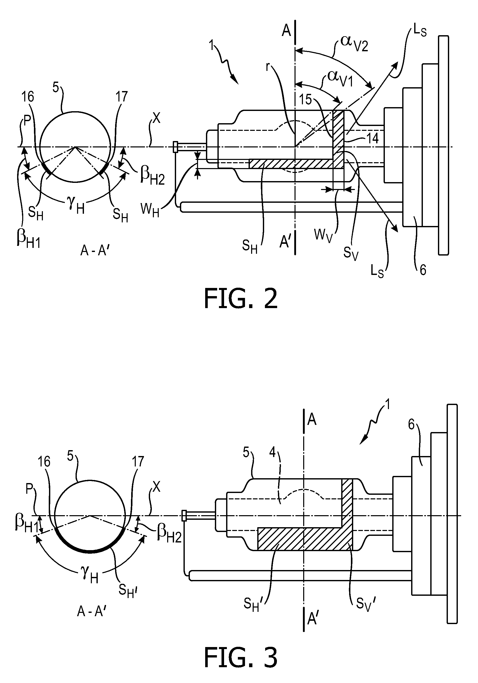
[0045]FIG. 1 shows a cross section of a prior art gas-discharge lamp 10, with a partial coating 11, 12 comprising a circumferentially arranged stripe 11 and a pair of longitudinally arranged stripes 12, 13. The lamp 10 shown corresponds to a D4R lamp, with a ballast 6 or base 6, for use in an automotive headlight assembly. The width of the circumferential stripe 11 is defined in the appropriate regulation, in this case ECE R99, by the angles α1, α2 subtended at the lamp centre between a radius r and points on the outer edges of the circumferential stripe 11. The regulation ECE R99 requires that the smaller angle α1 be 45°±5°, and that the larger angle α2 be at least 70°. On a D4R lamp, such a circumferential stripe 11 can therefore have a width of about 8.3 mm, and usually covers a substantial part of the underlying pinch region. A pair of longitudinal stripes 12, 13 is arranged one of each side of the lamp 10. This is illustrated in the cross-section A-A′ shown on the left of the d...


PUM


Abstract

The invention describes a gas-discharge lamp (1) comprising a vessel (5), which vessel is partially coated with an essentially rectangular stripe (Sv) arranged circumferentially on a surface of the vessel, and wherein a first long side (14) of the stripe is situated close to a base (6) of the lamp, and the width (wv) of the stripe is such that a first angle (αv2) subtended at a lamp center between a radius (r) and a point on the first long side (14) of the stripe comprises at most 55°, and a second angle (αv1) subtended at the lamp center between the radius and a point on a second long side (15) of the stripe comprises at most 50°. The invention also describes a reflector for a lamp, comprising a reflective interior surface realized to deflect light originating from the lamp outward to give a specific beam profile with a bright / dark cutoff line and a shoulder, and wherein the lamp, in particular a lamp as described above, is positioned horizontally in the reflector, and wherein the reflective interior surface comprises at least one beam-shaping region realized to deflect a portion of the light emitted from the lamp between 7.5° and 15° below a horizontal plane, at a specific region within the beam profile.

Description

FIELD OF THE INVENTION[0001]The invention describes a gas discharge lamp, a reflector, and a lighting assembly.BACKGROUND OF THE INVENTION[0002]High-intensity discharge lamps (HID lamps) are widely used in automotive headlamp applications, since they can provide an intensely bright light. To ensure traffic safety, characteristics of such lamps such as beam profile, colour temperature, lamp driver characteristics, lamp dimensions, etc., are specified in different countries by the appropriate regulations. For example, in Europe, the beam profile that is to be emitted by a headlamp, i.e. the shape of the low (passing) beam and the shape of the high (driving) beam, is regulated by ECE-R98, where ‘ECE’ stands for ‘Economic Commission for Europe’, while design-specific aspects of discharge light sources for use in such headlamps are regulated by ECE-R99. Often, the lamps specified in these regulations are simply referred to by their designation, e.g. ‘D3S’, ‘D4R’, etc.[0003]An R-type lamp...

Claims


Application Information

Patent Timeline
Patent Type & Authority Patents(United States)
IPC IPC(8): H01J61/34H01J61/35H01K1/32F21S8/10
CPCH01J61/35H01J61/34H01K1/32F21S48/1186F21S48/145H01K1/325F21S48/1358F21S41/334F21S41/43F21S41/172
Inventor KUEPPER, LUKASHAACKE, MICHAELSCHOELLER, KLAUS
Owner LUMILEDS
Why Eureka
Try Eureka