Stabilized intervertebral scaffolding systems

a scaffolding system and intervertebral technology, applied in the field of intervertebral scaffolding systems, can solve the problems of preventing the fusion of the intervertebral space, unable to provide a path for bone graft insertion, and unable to fill the space surrounding the cag

Active Publication Date: 2015-06-23
INTEGRITY IMPLANTS INC
View PDF132 Cites 126 Cited by
  • Summary
  • Abstract
  • Description
  • Claims
  • Application Information

AI Technical Summary

Benefits of technology

[0021]The step of creating the point of entry can comprise creating a lateral dimension of the point of entry ranging from about 5 mm to about 15 mm, and the amount of lateral expansion can be selected to exceed the lateral dimension of the point of entry. The step of expanding can include expanding the laterovertically expanding frame laterally to a width that exceeds the width of the point of entry; and, inserting the central beam to expand the laterovertically expanding frame vertically to support the frame in the expanded state. The step of inserting the central beam into the laterovertically expanding frame includes engaging a means for preventing the central beam from backing out of the laterovertically-expanding frame after the expanding.

Problems solved by technology

Unfortunately, therein lies a problem solved by the teachings provided herein.
Currently available systems can be problematic in that the methods of introducing the fusion cage and bone graft material leaves pockets in regions of the intervertebral space that are not filled with bone graft material, regions in which fusion is desired for structural support.
These pockets can create a premature failure of the fused intervertebral space due to forces that are distributed through the regions containing the pockets, for example, when the patient stands and walks.
However, this makes it difficult to insert and position properly.
Unfortunately, these types of devices have the typical graft distribution problem discussed above, in that they do not provide a path for bone graft to be inserted and fill in the space surrounding the cage or within the cage.
They have other problems as well, including that the annulotomy must be large to accommodate a large enough cage for stability, and this large opening necessitates more trauma to the patient.
Moreover, they can also create the additional problem of “backout”, in that they cannot expand laterally beyond the annulotomy to increase the lateral footprint of the cage relative to lateral dimension of the annulotomy.
Since it takes several months for the fusion to occur to completion in a patient, the devices have plenty of time to work their way out of the space through the large annulotomy.
Scaffolding systems may also suffer a lack of stability and / and or a lack of a retention of structural components in a desired expansion configuration in the intervertebral space.

Method used


Image

  • Stabilized intervertebral scaffolding systems
  • Stabilized intervertebral scaffolding systems
  • Stabilized intervertebral scaffolding systems

Examples


Embodiment Construction

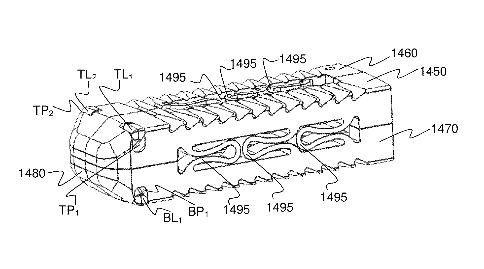
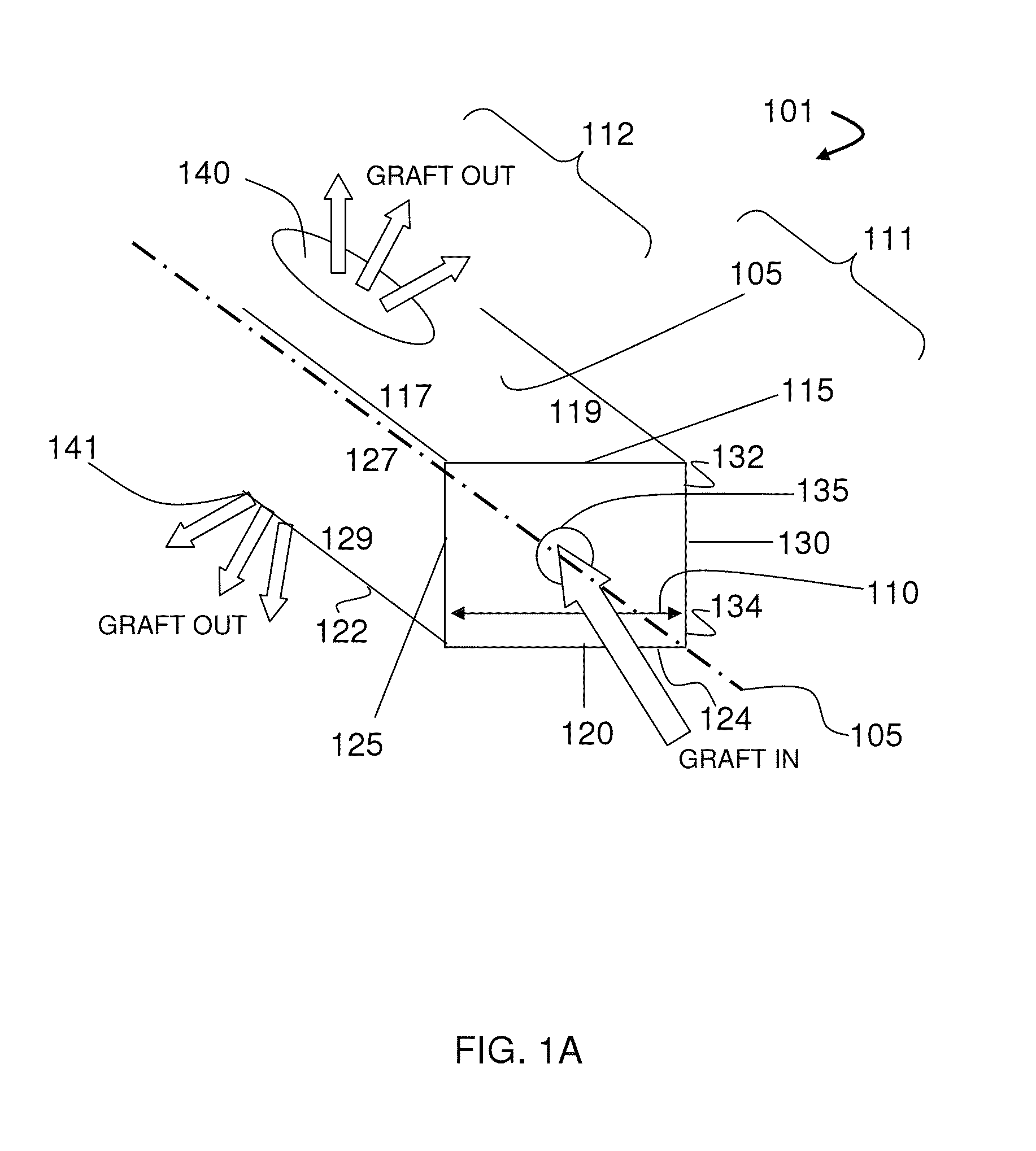
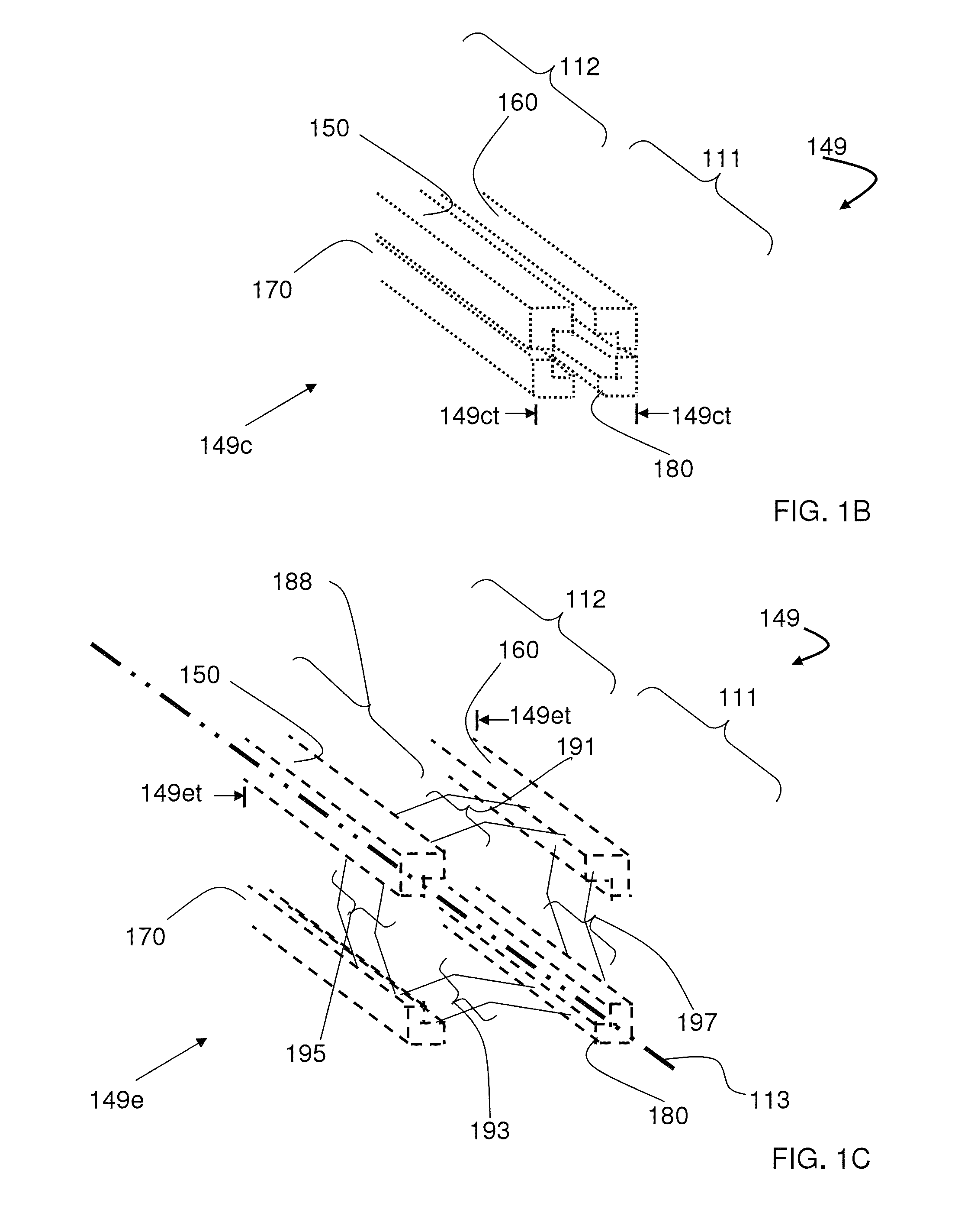
[0038]The teachings herein are directed to intervertebral scaffolding systems having a stabilizer for stabilizing and / or retaining support beams upon expansion of the scaffolding in an intervertebral disc space. The systems can have, for example, a central beam having a proximal portion having an end, a grafting portion having a top and a bottom, a distal portion having a end, a central beam axis, a graft distribution channel having an entry port at the end of the proximal portion, a top exit port at the top of the grafting portion, and a bottom exit port at the bottom of the grafting portion. These systems can also include a laterovertically-expanding frame having a lumen, a first top beam, a second top beam, a first bottom beam, and a second bottom beam, each having a proximal portion and a distal portion, and each operably connected to each other at their respective proximal portions and distal portions with connector elements to form the laterovertically-expanding frame that is ...


PUM


Abstract

An intervertebral scaffolding system is provided having a central beam having a proximal portion having an end, a grafting portion having a top and a bottom, a distal portion having a end, a central beam axis, a graft distribution channel having an entry port at the end of the proximal portion, a top exit port at the top of the grafting portion, and a bottom exit port at the bottom of the grafting portion. These systems can also include a laterovertically-expanding frame operable for a reversible collapse from an expanded state into a collapsed state. The expanded state, for example, can be configured to have an open graft distribution window that at least substantially closes upon the reversible collapse.

Description

BACKGROUND[0001]1. Field of the Invention[0002]The teachings herein are directed to intervertebral scaffolding systems having a stabilizer for stabilizing and / or retaining support beams upon expansion of the scaffolding in an intervertebral disc space.[0003]2. Description of the Related Art[0004]Bone grafts are used in spinal fusion, for example, which is a technique used to stabilize the spinal bones, or vertebrae, and a goal is to create a solid bridge of bone between two or more vertebrae. The fusion process includes “arthrodesis”, which can be thought of as the mending or welding together of two bones in a spinal joint space, much like a broken arm or leg healing in a cast. Spinal fusion may be recommended for a variety of conditions that might include, for example, a spondylolisthesis, a degenerative disc disease, a recurrent disc herniation, or perhaps to correct a prior surgery.[0005]Bone graft material is introduced for fusion and a fusion cage can be inserted to help suppor...

Claims


Application Information

Patent Timeline
Patent Type & Authority Patents(United States)
IPC IPC(8): A61F2/44A61F2/46A61F2/30
CPCA61F2/447A61F2/4611A61F2002/30545A61F2002/4677A61F2002/30476A61F2/442A61F2/4455A61F2002/2835A61F2002/30471A61F2002/30556A61F2002/30579
Inventor TO, JOHNFLYNN, JOHN J.
Owner INTEGRITY IMPLANTS INC
Why Eureka
Try Eureka