Method of disposing a linearly expandable ureteral stent within a patient

a ureteral stent and linear expansion technology, applied in the field of ureteral stents, can solve the problems of threatening renal function, pain from trigome irritation, discomfort of stents, etc., and achieve the effects of facilitating fluid drainage, minimizing pain and discomfort, and maintaining the patency of the ureter

Active Publication Date: 2015-06-23
BOSTON SCI SCIMED INC
View PDF87 Cites 32 Cited by
  • Summary
  • Abstract
  • Description
  • Claims
  • Application Information

AI Technical Summary

Benefits of technology

[0007]It is an objective of the invention to provide a patient, male or female, with a flexible device designed to maintain the patency of the ureter and enable fluid drainage while minimizing the pains and discomfort commonly associate with an in-dwelling device.
[0008]Discomfort may be related to the stent rubbing against a wall of the ureter, caused by the constant relative motion between the kidney and the bladder. This motion may be as much as 5 centimeters (cm) (approximately 2 inches) and cycles with each breath of the patient. This is equal to approximately 17,000 cycles per day, assuming 1 breath every 5 seconds. The present invention alleviates discomfort by providing a stent that, like the ureter, linearly expands and contracts in response to relative motion between the kidney and the bladder, thereby reducing friction caused by a stent rubbing against a wall of the ureter.
[0015]In yet another aspect of the invention, a method of facilitating urinary drainage from a kidney to a bladder in a patient that reduces discomfort to the patient includes positioning a ureteral stent in a ureter of a patient, the ureteral stent having an elongated member defining a lumen, the member having a solid sidewall defining a spiral-shaped opening such that the member is linearly expandable along a longitudinal axis of the lumen, a distal retention structure connected to a distal end of the elongated member for retention in the kidney, and a proximal retention structure connected to a proximal end of the elongated member for retention in the bladder. The elongated member is allowed to linearly expand and contract between an expanded position and a retracted position, based on at least one of: relative positioning of organs within the patient, a breathing pattern of the patient, and relative positions of the kidney and the bladder. In addition, the elongated member can be biased to the retracted position.

Problems solved by technology

Serious obstructions may cause urine to back up into the kidneys, threatening renal function.
A stent may be uncomfortable to a patient because of intramural tunnel pain, imposed by the stent itself or in combination with intraoperative trauma inflicted from device passage.
Further, pain may stem from trigome irritation resulting from constant irritation, imposed by the bladder anchoring features or in combination with intraoperative trauma inflicted from device passage.
Moreover, discomfort may arise from flank pain, caused by reflux or kidney anchoring.

Method used


Image

  • Method of disposing a linearly expandable ureteral stent within a patient
  • Method of disposing a linearly expandable ureteral stent within a patient
  • Method of disposing a linearly expandable ureteral stent within a patient

Examples


Embodiment Construction

[0028]The invention features temporary ureteral stents that, when positioned within the ureter of a patient, significantly reduce discomfort to the patient. As used herein, proximal refers to the end of a stent closest to a medical professional when placing a stent in a patient. As used herein, distal refers to the end of a stent furthest from a medical professional when placing a stent in a patient.

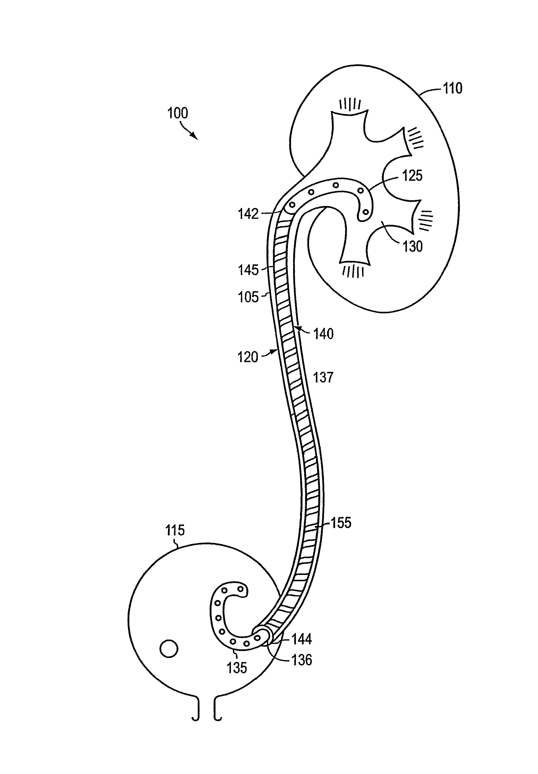
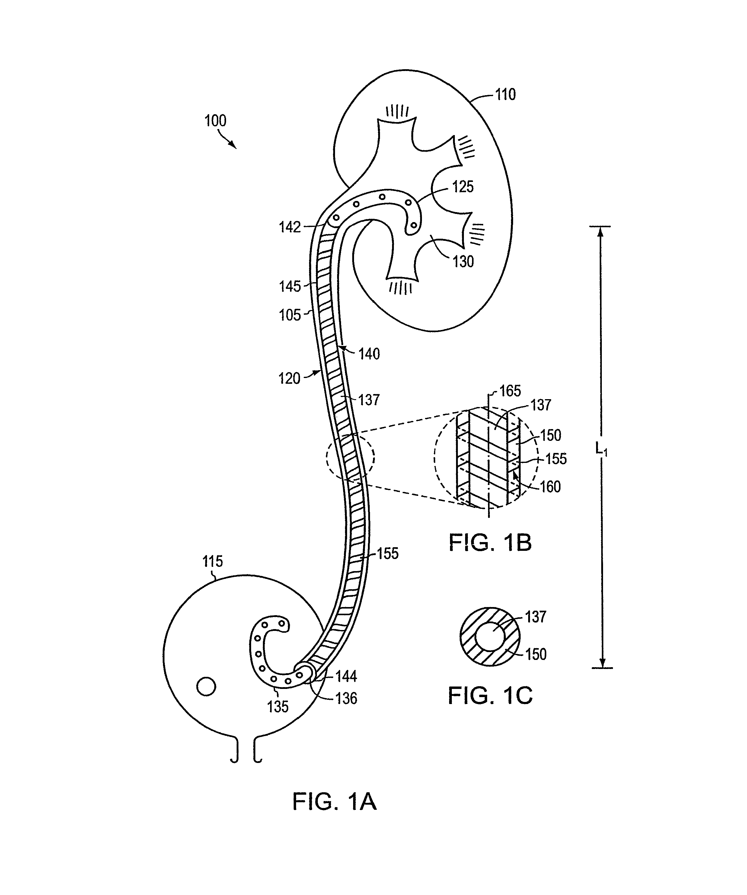
[0029]Referring to FIG. 1A, a human urinary tract 100 includes a ureter 105 that transports urine from a kidney 110 to a bladder 115. When ureter 105 becomes blocked or obstructed due to, for example, post-kidney stone fragmentation / removal and ureteral stricture therapy, fluid drainage can become restricted. Ureteral stents are medical devices that are implanted within ureter 105 to restore patency and fluid drainage. A ureteral stent 120 is located within the ureter 105 of a patient, with a distal retention structure 125 in a pelvis 130 of kidney 110, and a proximal retention structure...


PUM


Abstract

A method includes placing a ureteral stent on an insertion tool. The ureteral stent includes an elongate member having a distal end coupled to a distal retention member. The elongate member includes a solid spring wire having a plurality of coils defining a lumen. A first portion of the insertion tool is disposed within the lumen, and the distal retention member, which has a nominally curved shape, is disposed about a second portion of the insertion tool such that the distal retention member is substantially linear. The insertion tool is inserted into the body of the patient and the ureteral stent is moved along the insertion tool such that at least a portion of the distal retention member is disposed within the kidney and a portion of the elongate member is disposed within the ureter.

Description

CROSS-REFERENCE TO RELATED APPLICATIONS[0001]This application is a divisional of U.S. patent application Ser. No. 10 / 283,873, entitled “Linearly Expandable Ureteral Stent,” filed Oct. 30, 2002 (now abandoned), the entirety of which is incorporated herein by reference.BACKGROUND[0002]The invention generally relates generally to medical devices for the drainage of fluids, and more specifically to ureteral stents.[0003]A ureter is a tubular passageway in a human body that conveys urine from a kidney to a bladder. The ureter begins with the renal pelvis and ends at the trigone region of the bladder, i.e., the triangulated area between both ureteral orifices and the bladder neck. Urine is transported through the ureter under the influence of hydrostatic pressure, assisted by contractions of muscles located within the walls (lining) of the ureter. Some patients experience a urological condition known as ureteral blockage or obstruction. Some common causes of ureteral blockage are the form...

Claims


Application Information

Patent Timeline
Patent Type & Authority Patents(United States)
IPC IPC(8): A61F2/04A61M27/00A61F2/88A61M25/00
CPCA61F2/88A61F2/04A61M27/008
Inventor GELLMAN, BARRY N.
Owner BOSTON SCI SCIMED INC
Why Eureka
Try Eureka