Multi-port valve device with dual directional strainer

a valve device and dual-directional technology, applied in the field of valve devices, can solve the problems of clogging or damage both injection pumps, time-consuming and labor-intensive assembly of such systems, and not providing means, so as to reduce the number of threaded connection points, reduce the number of leak paths, and reduce the number of fittings

Active Publication Date: 2015-06-23
WINBORN CRAIG V
View PDF12 Cites 29 Cited by
  • Summary
  • Abstract
  • Description
  • Claims
  • Application Information

AI Technical Summary

Benefits of technology

[0016]The device disclosed herein includes a novel one-piece valve device. By utilizing this one-piece device, the disclosed device provides a device having a reduced number of fittings, a reduced number of threaded connection points, and a reduced number of leak paths. This configuration provides many advantages over current assemblies used to connect an injection system to a tank. Unlike existing systems used to connect an injection system to a tank, the present device is not comprised of multiple threaded pipe fittings that must be threadably connected to one another at the work site. The present device provides for a quick and easy installation method and saves time and labor costs by significantly reducing the number of threaded connection points between the tank and the injection system. Additionally, by eliminating many of the threaded connection points and leak paths, the configuration of the disclosed device greatly reduces the waste resulting from leaks of hydraulic fracturing fluids and decreases the environmental and human health risks associated with such leaks.
[0017]Furthermore, unlike current assemblies that utilize pipe fittings designed to handle pressurized fluids, the disclosed device is designed to handle the non-pressurized fluids flowing by gravity from the tank to the injection pump. Therefore, the disclosed device is designed to be more compact and has thinner walls and a reduced weight compared to current assemblies.

Problems solved by technology

Such pipe fittings are not specifically made for connecting a tank to an injection pump and to a gauge, and as a result, present several disadvantages.
One problem with current systems is that such systems do not provide a means to simultaneously filter the fluids flowing from the tank to the injection pump and flowing from the tank to the gauge.
Such fluids often include particulates, dirt, and other unwanted materials that can clog or damage both the injection pump and the gauge.
Another problem with current systems is that the assembly of such systems is time-consuming and labor intensive.
Therefore, much time and effort is spent trying to properly thread the various pipe fittings together in an effort to make leak-proof, reliable connections between the fittings.
A further problem with current systems is that each threaded connection point between the pipe fittings is a potential leak path.
In reality, complete metal-to-metal contact between the male and female threads is extremely difficult to achieve and any minute spaces left in between the threads become leak paths.
This is a serious problem faced by the oil and gas industry as surface leaks of undiluted fluids used in hydraulic fracturing result in waste of expensive fluids and pose great risks to the environment and human health.
Another problem with current systems is the unnecessary stress placed upon tanks due to the use of heavy pipe fittings designed to handle pressurized fluids.
Therefore, current pipe fittings have thicker and sturdier walls and, thus, weigh more than required for handling non-pressurized fluids, such as the fluids flowing from the tank to the injection pump.
As a result of the added weight and stress placed upon tanks by current systems, current systems decrease the life span of tanks.

Method used


Image

  • Multi-port valve device with dual directional strainer
  • Multi-port valve device with dual directional strainer
  • Multi-port valve device with dual directional strainer

Examples


Embodiment Construction

[0029]The terms “top,”“bottom,”“front,” and “rear” are used in the specification to describe the embodiments of the invention as illustrated in the accompanying Figures. It should be appreciated that in actual use, an embodiment of the invention may be rotated as needed to accomplish the objectives of the invention. As a result of such rotation, the various terms used herein of “top,”“bottom,”“front,”“rear,” and the like may not literally apply to a particular arrangement. Such terms are relative and are used herein to describe the Figures for illustration purposes only and are not intended to limit the embodiments shown to any particular orientation.

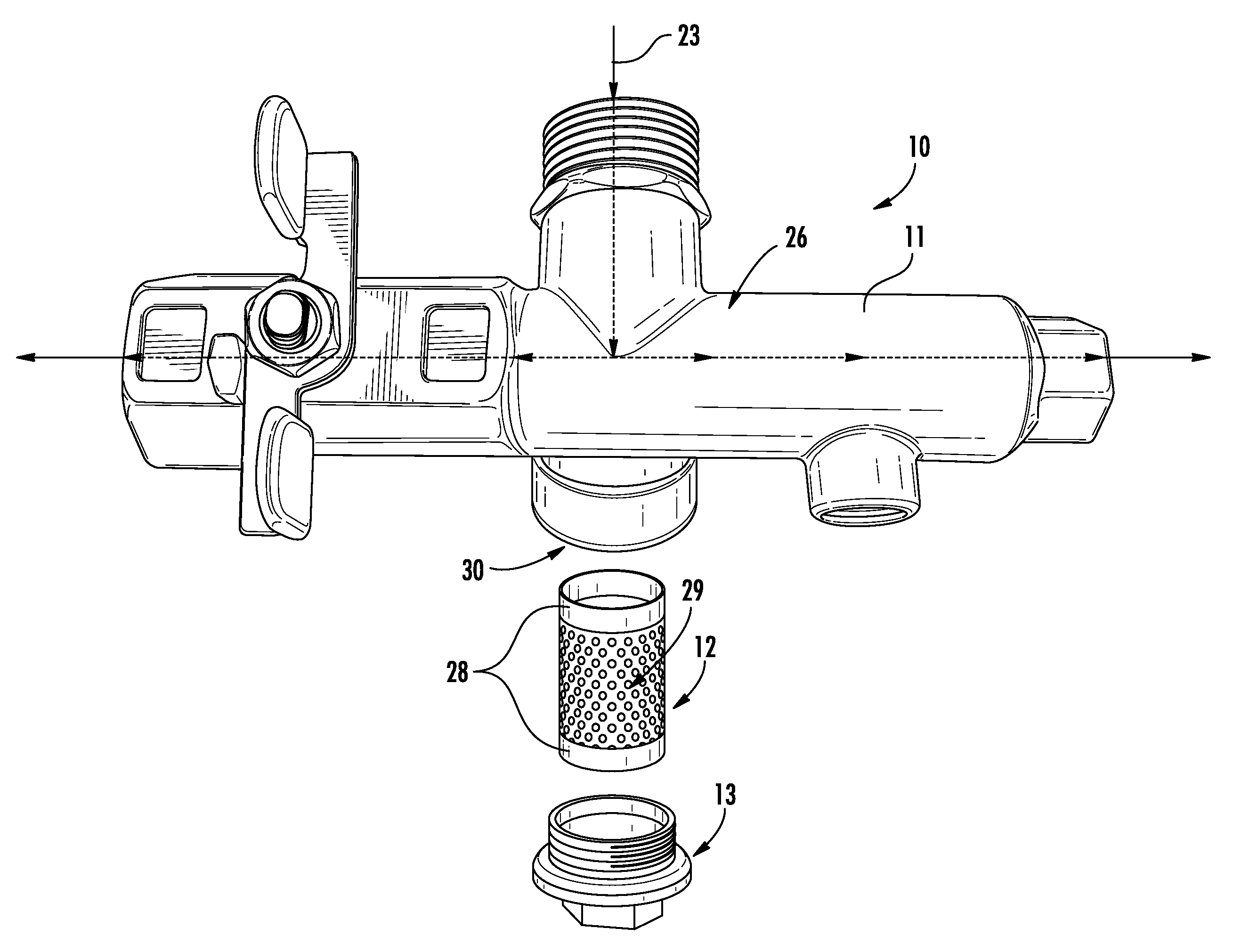
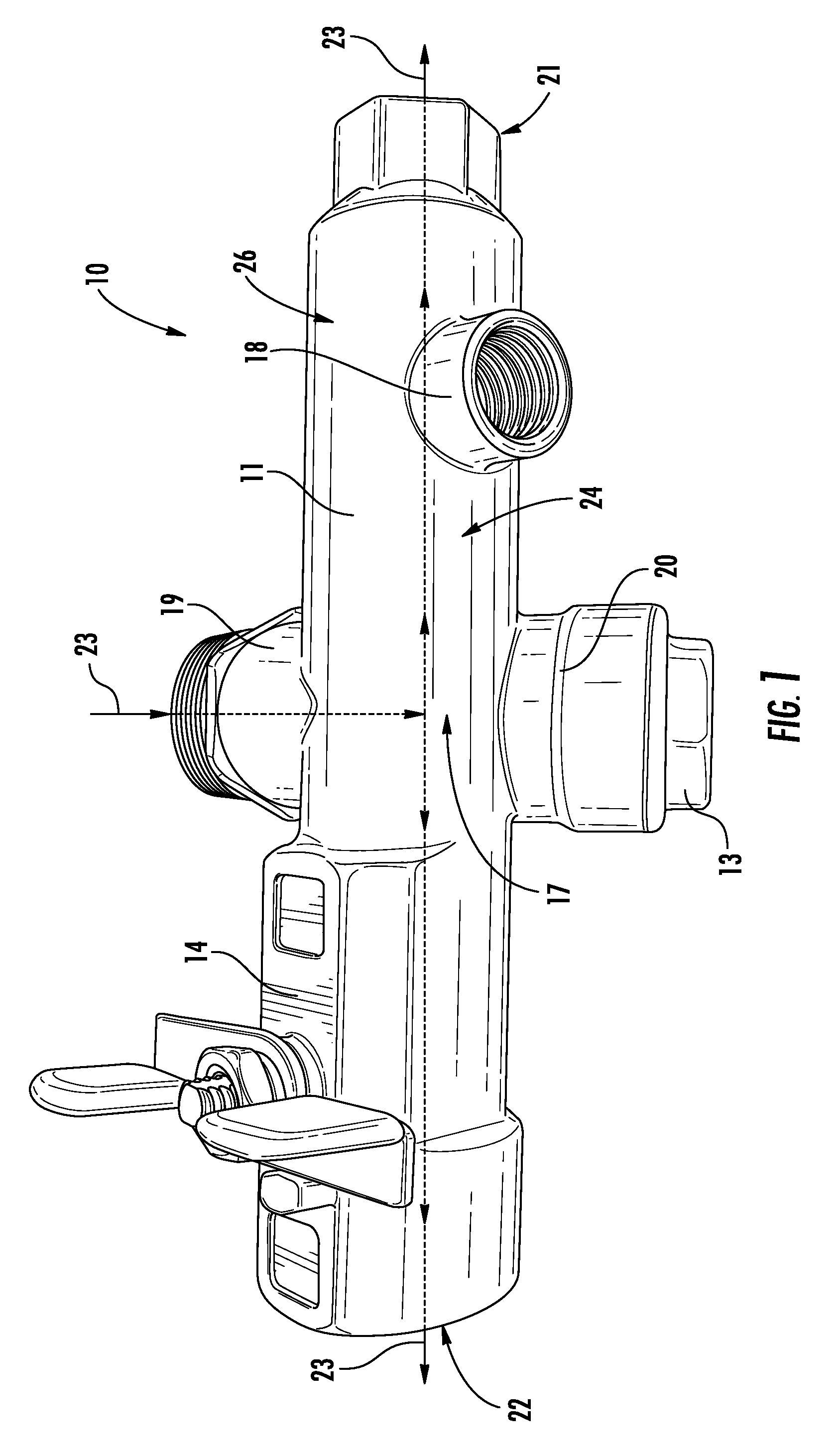
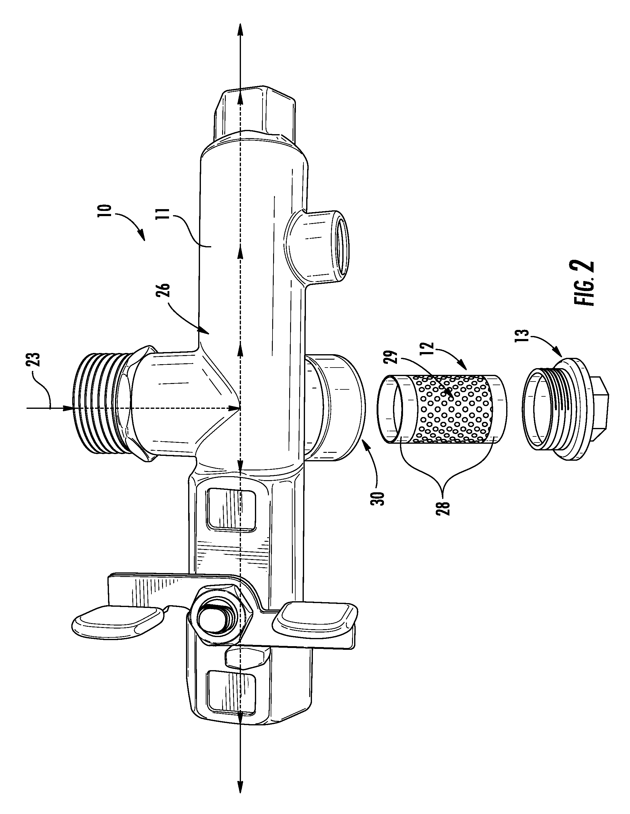
[0030]Referring now to FIGS. 1-9, exemplary embodiments of a multi-port valve device with dual directional strainer 10 in accordance with the present disclosure are illustrated. The valve device 10 is configured to fluidly connect a tank to an injection pump and to a gauge.

[0031]As illustrated in the accompanying Figures, the valve devi...


PUM

PropertyMeasurementUnit
thickaaaaaaaaaa
thickaaaaaaaaaa
angleaaaaaaaaaa

Abstract

A multi-port valve device with a dual directional strainer is disclosed herein. The disclosed valve device generally comprises a body including a cylindrical wall, the body having a front face, a rear face, a top face, and a bottom face; a first arm including a cylindrical wall, wherein the first arm is attached to the rear face of the body and extends perpendicularly from the rear face of the body; a second arm including a substantially cylindrical wall, wherein the second arm is attached to the bottom face of the body and extends obliquely from the bottom face of the body; a fluid passageway extending through the cylindrical walls of the first arm and the body; and a strainer member at least partially disposed within the second arm, the strainer member being arranged and configured to strain fluids flowing through the fluid passageway from the first arm through the strainer member and into the body in a first direction and to strain fluids flowing from the first arm through the strainer member and into the body in a second direction, the second direction being opposite of the first direction. The disclosed valve device may be utilized to fluidly connect a tank to an injection pump and to a gauge.

Description

CROSS-REFERENCE TO RELATED APPLICATIONS[0001]This application is related to and claims priority from earlier filed U.S. Provisional Patent Application No. 62 / 049,553, filed Sep. 12, 2014, the disclosure of which is incorporated herein by reference.BACKGROUND OF THE INVENTION[0002]1. Field of the Invention[0003]The present invention generally relates to a valve device and method of use. More specifically, the present invention relates to a multi-port valve device with a dual directional strainer, which may be used for connecting an injection pump system to a tank.[0004]2. Description of Related Art[0005]Hydraulic fracturing is widely used in the oil and gas industry to enhance recovery of oil and natural gas. Commonly known as “fracking,” hydraulic fracturing is the propagation of fractures in a rock layer by a pressurized fluid. Hydraulic fractures are formed by drilling wellbores into reservoir rock formations and injecting large volumes of fracking fluid, primarily consisting of w...

Claims


Application Information

Patent Timeline
Patent Type & Authority Patents(United States)
IPC IPC(8): F16K11/20F16K27/06B01D35/02B01D46/00B01D29/92
CPCB01D29/92B01D46/0039B01D35/02F16K11/20F16K27/06Y10T137/794B01D35/28
Inventor WINBORN, CRAIG V.
Owner WINBORN CRAIG V
Why Eureka
Try Eureka