Hydraulic vehicle brake system

a brake system and hydraulic technology, applied in the direction of electrodynamic brake systems, brake systems, vehicle components, etc., can solve the problems of high quality blending, complex and difficult effects of electric machines in generator mode, if any, and achieve the effect of simple modifications and simple manner

Inactive Publication Date: 2015-06-23
ROBERT BOSCH GMBH
View PDF19 Cites 4 Cited by
  • Summary
  • Abstract
  • Description
  • Claims
  • Application Information

AI Technical Summary

Benefits of technology

[0004]The vehicle brake system according to the invention can be implemented by relatively simple modifications to a conventional slip-controlled vehicle brake system. It is provided especially for electric or hybrid vehicles, that is to say for motor vehicles which have one (or more) electric drive motors or, more generally, one (or more) electric machines, to be precise rotary electric machines which can be operated as generators and, in the process, produce electric energy, which is stored in an accumulator and is available for driving the vehicle. Electric machines include not only electric motors but also generators. During braking, the electric machine is operated as a generator and produces a braking torque. It is possible for a vehicle driver to compensate for the braking torque of the electric machine. In more refined systems, the braking torque of the electric machine in generator mode is fully or partially compensated by a reduction in the braking force of the vehicle brake system. Compensating for the braking torque of the electric machine in generator mode by reducing the braking force of the vehicle brake system is also referred to as “blending”. High-quality blending, in which a vehicle driver hardly notices the effect of the electric machine in generator mode, if at all, is complex and difficult. The invention enables high-quality blending in a relatively simple manner by open-loop or closed-loop control of the brake pressure in the additional, independently powered brake circuit, which is not connected to the brake master cylinder.
[0005]The dependent claims relate to advantageous embodiments and refinements of the invention indicated in claim 1.

Problems solved by technology

High-quality blending, in which a vehicle driver hardly notices the effect of the electric machine in generator mode, if at all, is complex and difficult.

Method used


Image

  • Hydraulic vehicle brake system
  • Hydraulic vehicle brake system

Examples


Embodiment Construction

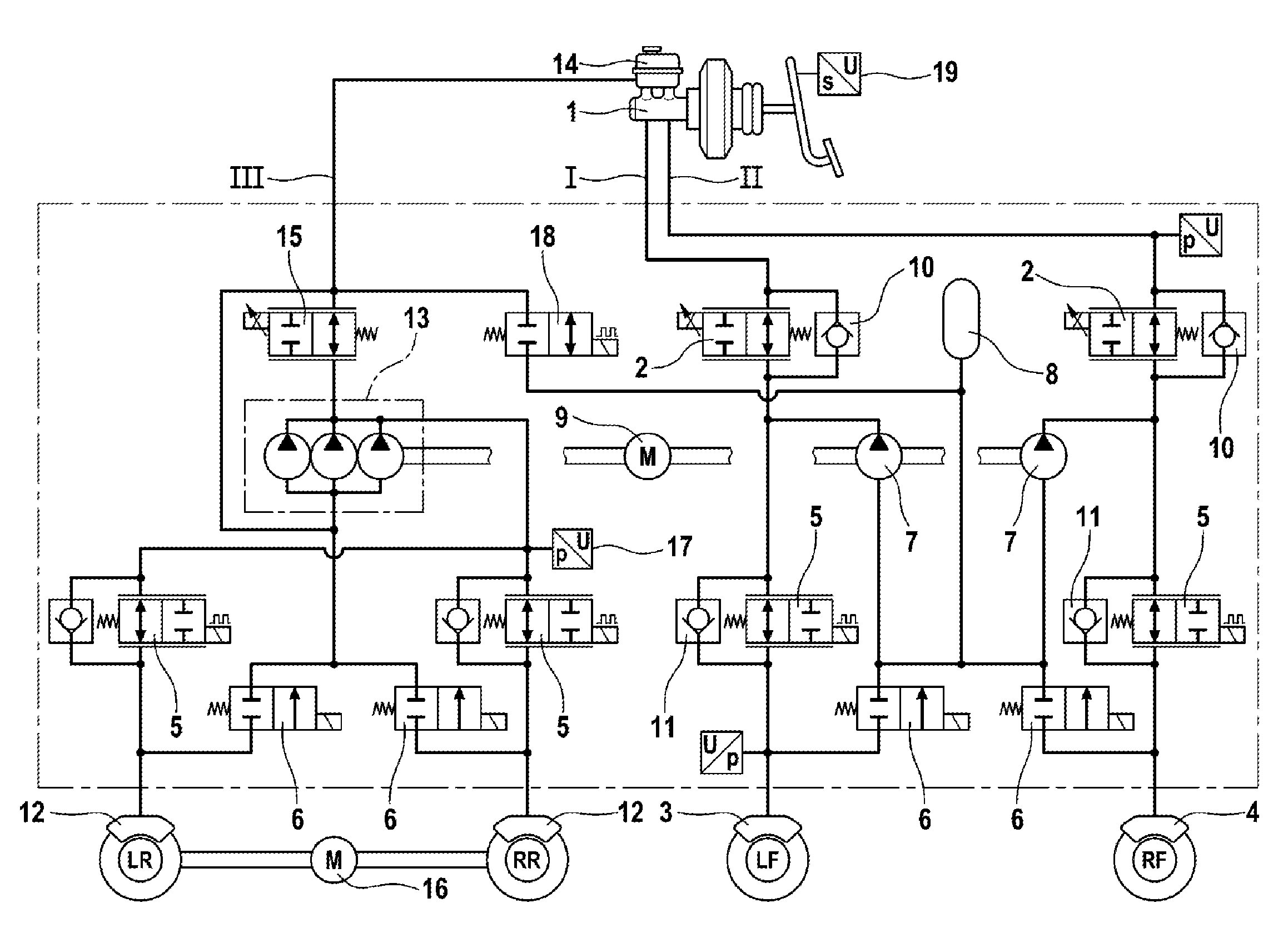
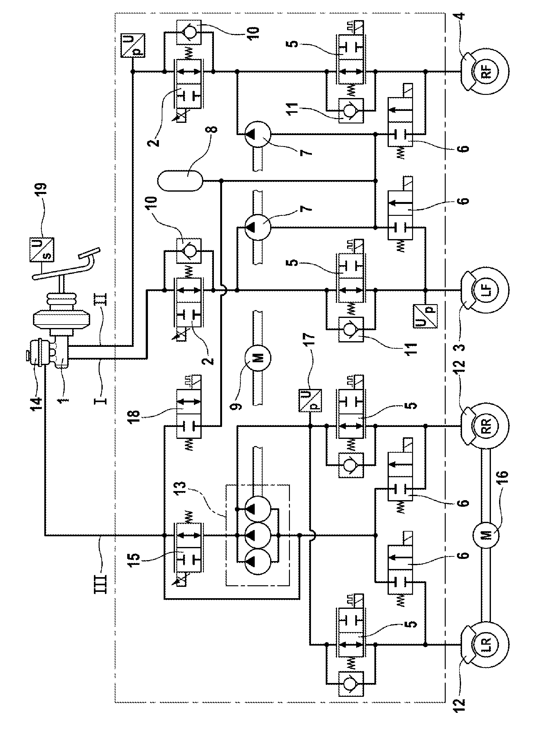
[0007]The hydraulic vehicle brake system according to the invention shown in the drawing has a dual-circuit brake master cylinder 1, to which two brake circuits I, II are connected via isolating valves 2. One hydraulic wheel brake 3, 4 of a vehicle axle is connected to each of the two brake circuits I, II. In the illustrative embodiment, the wheel brakes 3, 4 of a front axle are connected to the two brake circuits I and II, which are connected to the brake master cylinder 1. However, it is not essential to the invention that the wheel brakes of the front axle should be connected to the brake master cylinder 1. For each wheel brake 3, 4, brake circuits I, II have a brake pressure buildup valve 5, by means of which the wheel brake 3, 4 is connected to the isolating valve 2, and a brake pressure reducing valve 6, by means of which the wheel brake 3, 4 is connected to the intake side of a hydraulic pump 7 and to a hydraulic accumulator 8. There is a hydraulic pump 7 in each of the two b...


PUM


Abstract

A hydraulic vehicle brake system, preferably a slip-controlled hydraulic vehicle brake system, includes two brake circuits to which wheel brakes of front wheels are attached. The brake system further includes an additional brake circuit, which is not attached to the main brake cylinder, but is provided with a hydraulic pump for power braking. Wheel brakes of vehicle wheels are attached to the additional brake circuit and are configured to be driven by an electric motor. The electric motor is operated as a generator during a braking operation to compensate for the braking moment generated in the additional brake circuit.

Description

[0001]The invention relates to a hydraulic vehicle brake system having the features of the preamble of claim 1.PRIOR ART[0002]Hydraulic vehicle brake systems for motorcars generally have a dual-circuit brake master cylinder, to which hydraulic wheel brakes are connected. Various ways of splitting brake circuits are known, the term “splitting” brake circuits referring to the connection of the individual wheel brakes to the two brake circuits. Slip-controlled vehicle brake systems have brake pressure buildup and brake pressure reducing valves, by means of which wheel brake pressures in the wheel brakes can be subjected to open-loop or closed-loop control. In slip-controlled vehicle brake systems, there is furthermore a hydraulic pump in each brake circuit. Anti-lock, traction control and stability control operations, for which abbreviations such as ABS, ASR, VDC and ESP are customary, are carried out. These control operations are known to a person skilled in the art and will not be ex...

Claims


Application Information

Patent Timeline
Patent Type & Authority Patents(United States)
IPC IPC(8): B60T13/00B60T8/26B60T13/16B60T8/48
CPCB60T13/161B60T8/267B60T8/4872B60L7/26B60T8/48B60T8/40B60T8/26
Inventor STRENGERT, STEFANKUNZ, MICHAEL
Owner ROBERT BOSCH GMBH
Why Eureka
Try Eureka