Parallel double clutch device and drivetrain having a parallel double clutch device of said type

a technology of parallel double clutch and drivetrain, which is applied in the direction of clutches, non-mechanical actuated clutches, climate sustainability, etc., can solve the problems of increased leakage losses, complex design of known parallel double clutch devices, and large installation space occupation, so as to achieve high operating pressure, substantially leakage-free operation, and high leakage loss

Active Publication Date: 2015-06-23
BORGWARNER INC
View PDF8 Cites 0 Cited by
  • Summary
  • Abstract
  • Description
  • Claims
  • Application Information

AI Technical Summary

Benefits of technology

[0035]In a further particular embodiment of the parallel double clutch device according to the invention, which constitutes a refinement of the embodiment described above, the support of the double clutch device, particularly the input side thereof, in the axial and / or radial direction on the clutch housing or on the stationary support tube takes place via a rolling bearing, which is particularly a ball bearing. In this embodiment, the rolling bearing is particularly arranged in such a way as to support the parallel double clutch device, particularly the input side thereof, in both axial directions and in the radial direction on the clutch housing and on the stationary support tube.
[0018]To obtain particularly reliable decoupling in terms of rotational drive between the actuating piston and force-transmitting element in the above-described embodiment, the decoupling in terms of rotational drive between the actuating piston and the force-transmitting element takes place, in a further embodiment of the parallel double clutch device according to the invention, by an engagement bearing between the actuating piston and the force-transmitting element. By the engagement bearing and the inner rollers thereof, friction between the rotating force-transmitting element and the actuating piston which is decoupled in terms of rotational drive is substantially eliminated, such that a transmission of the rotational movement of the force-transmitting element to the actuating piston is substantially eliminated. In said embodiment, an exchangeable spacer is particularly provided between the actuating piston and the engagement bearing in the actuating direction of the actuating piston, such that the spacing between the actuating piston and engagement bearing in the actuating direction can be adjusted in a more flexible manner, and tolerance compensation can be carried out.
[0005]U.S. Pat. No. 7,246,692 B2 describes a parallel double clutch device having a first clutch arrangement and having a second clutch arrangement which are arranged in an axially staggered fashion, with the first clutch arrangement serving for the selective transmission of torque between a drive unit and a first transmission input shaft, while the second clutch arrangement serves for the selective transmission of torque between the drive unit and a second transmission input shaft. The two clutch arrangements can be actuated in each case by a hydraulically drivable actuating piston. For this purpose, each of the two actuating pistons is assigned a pressure chamber which is delimited by a pressure chamber housing and the respective actuating piston. The pressure chamber housing is formed in each case by a section of an inner rotating input hub of the parallel double clutch device. Furthermore, a compensating chamber for centrifugal oil compensation is provided on that side of each actuating piston which faces away from the pressure chamber. The abovementioned input hub of the parallel double clutch device is of substantially tubular design, with the tubular input hub being supported in the radial direction on a stationary support tube. To act on the pressure chambers with pressurized oil and thereby be able to drive the actuating piston, rotary leadthroughs are provided between the clutch input hub and the support tube, which rotary leadthroughs are separated from one another by corresponding rotary leadthrough seals.
[0016]In a further embodiment of the parallel double clutch arrangement according to the invention, to eliminate the need for arranging the respective actuating piston directly in the region of the associated clutch arrangement, and moreover to obtain a relatively free and installation-space-saving arrangement of the respective actuating piston, in each case one force-transmitting element is provided via which the respective clutch arrangement can be actuated by the associated actuating piston. In this way, the actuating piston may for example be arranged radially inside or outside the associated clutch arrangement in order, by corresponding nesting, to realize a shortening of the axial structural length of the parallel double clutch device.
[0008]The present invention overcomes the disadvantages in the related art in a parallel double-clutch device for arranging in a drivetrain of a motor vehicle between a drive unit and transmission of the drivetrain. The parallel double-clutch device comprises a first clutch arrangement assigned to a first transmission-input shaft for selectively transmitting torque between the drive unit and first transmission-input shaft. A second clutch arrangement is assigned to a second transmission-input shaft for selectively transmitting torque between the drive unit and second transmission-input shaft. The first clutch arrangement can be actuated by at least one hydraulically drivable first actuating piston that is assigned a first pressure chamber delimited by a first pressure-chamber housing and the first actuating piston. The second clutch arrangement can be actuated by at least one hydraulically drivable second actuating piston that is assigned a second pressure chamber delimited by a second pressure-chamber housing and the second actuating piston. The pressure-chamber housing is at least partially substantially stationary and / or rotationally fixed. The present invention overcomes the disadvantages in the related art also in a drivetrain of a motor vehicle that has the parallel double-clutch device.
[0021]In a further embodiment of the parallel double clutch device according to the invention, a stationary and / or rotationally fixed clutch housing is provided in which the double clutch device is arranged. Here, the clutch housing may be formed for example by a part of the transmission housing and / or a part of the engine housing.

Problems solved by technology

Firstly, the hydraulic system for driving the actuating piston is subject to leaks, such that the use of a high-pressure accumulator for increasing the efficiency of the parallel double clutch arrangement is duly possible but leads to increased leakage losses.
Secondly, the known parallel double clutch device has a complex design which takes up a large amount of installation space.

Method used


Image

  • Parallel double clutch device and drivetrain having a parallel double clutch device of said type
  • Parallel double clutch device and drivetrain having a parallel double clutch device of said type
  • Parallel double clutch device and drivetrain having a parallel double clutch device of said type

Examples


first embodiment

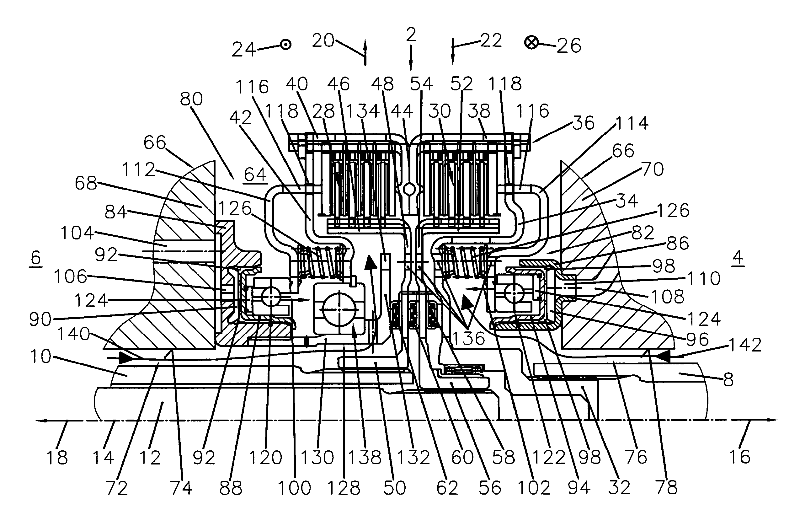
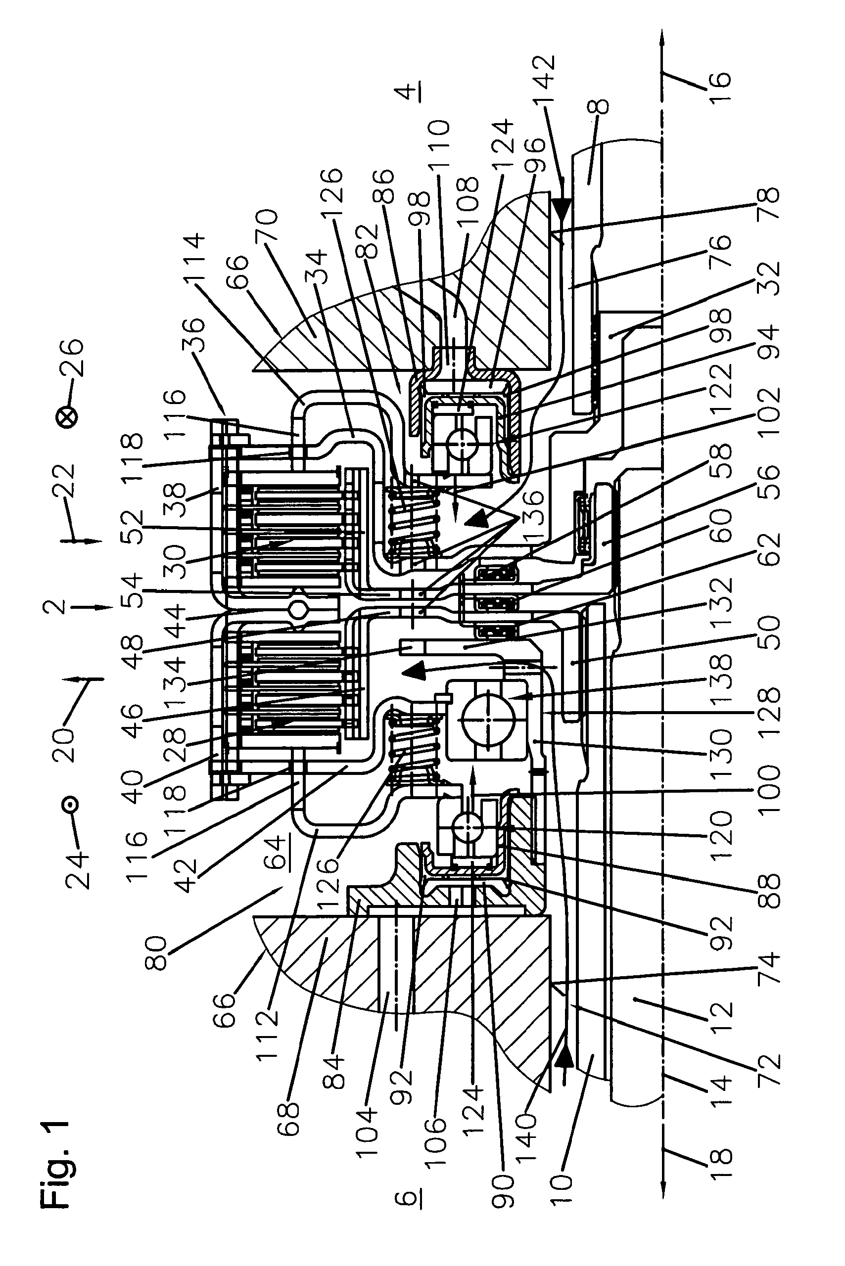
[0049]FIG. 1 shows the parallel double clutch device 2 within a drivetrain of a motor vehicle between a drive unit 4 and a transmission 6, wherein of the drive unit 4, which is for example an internal combustion engine, only the output hub 8 is illustrated, and of the transmission 6, which is particularly a double clutch transmission, only a first transmission input shaft 10 and a second transmission input shaft 12 are illustrated. The parallel double clutch device 2 is rotatable about a rotational axis 14 which extends in the axial directions 16, 18, with FIG. 1 also showing the mutually opposite radial directions 20, 22 and the mutually opposite circumferential directions 24, 26 with the aid of corresponding arrows. The first transmission input shaft 10 is designed as a hollow shaft through which the second transmission input shaft 12 extends coaxially. The two transmission input shafts 10, 12 are therefore arranged in a nested fashion in the radial direction 20, 22, such that the...

third embodiment

[0069]The input side of the parallel double clutch device 2 is composed substantially of the input hub 32, the first support section 34, the outer plate carrier 36 and the second support section 42. To now support said input side in the axial direction 16, 18 and / or radial direction 20, 22 on the clutch housing 66, a rolling bearing 138 is provided in the radial direction 20, 22 between the radially inwardly pointing end of the second support section 42 and the radially outwardly pointing side of the tubular section 130 of the support tube 128, which rolling bearing 138 is designed in the present example as a ball bearing. Here, the rolling bearing 138 is fixed in such a way that the abovementioned input side of the parallel double clutch device 2 is or can be supported in both radial direction 20, 22 on the first housing section 68 of the clutch housing 66 via the support tube 128 and the first pressure chamber housing 84. Furthermore, the rolling bearing 138 is fixed and arranged ...

fourth embodiment

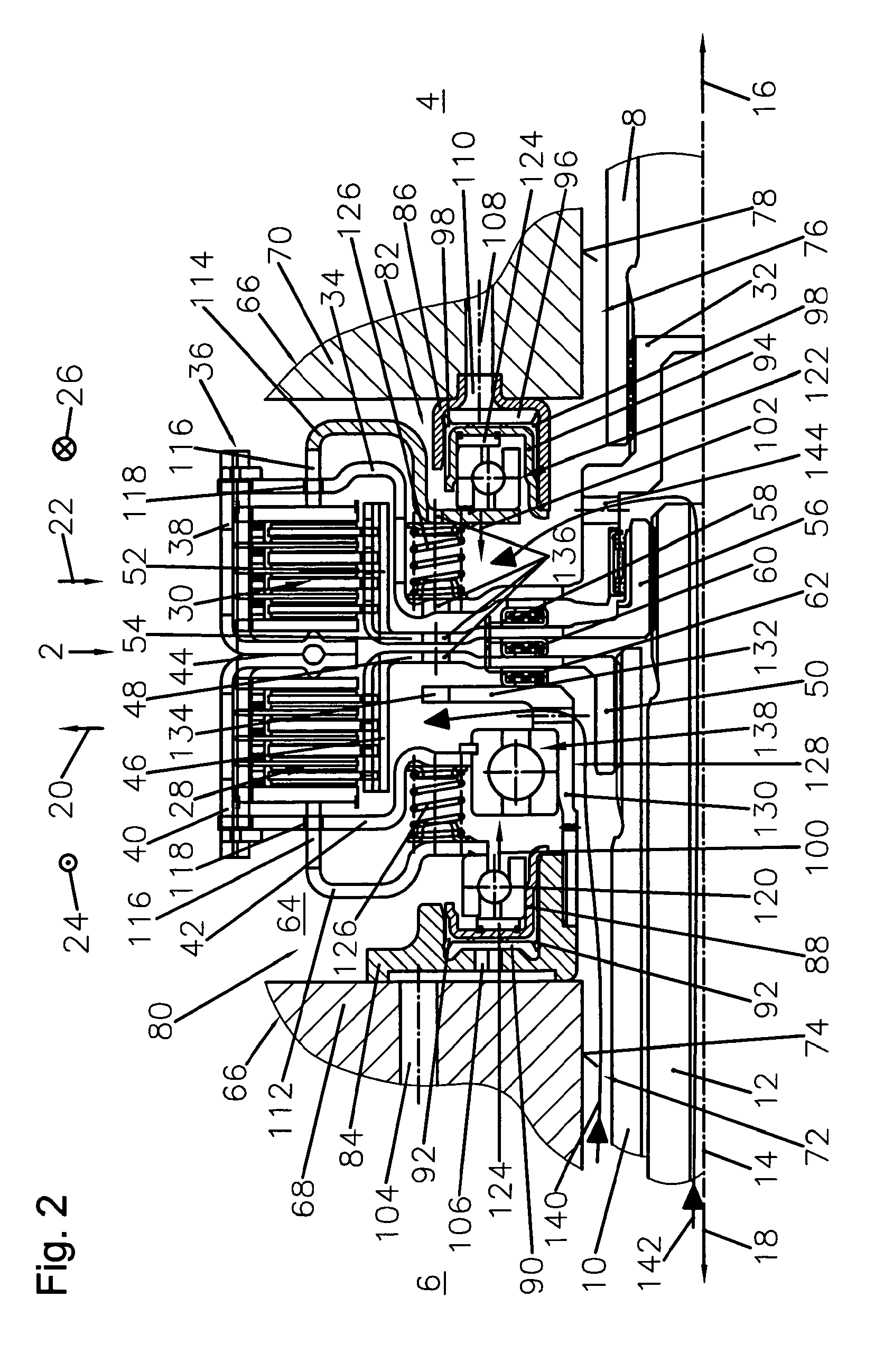
[0078]In the fourth embodiment, the support tube 128 is dispensed with. The second support section 42 of the input side is in fact supported in the radial direction 20, 22 on the outwardly pointing side of the first clutch output hub 50 via a tubular hub 146 and an interposed bearing 148. To support the input side of the parallel double clutch device 2 in the radial direction 20, 22 on the stationary clutch housing 66, a rolling bearing 150 is also provided in the shaft passage opening 76, which rolling bearing 150 is supported at one side in the radial direction 20 on the edge 78 of the shaft passage opening 76 and at the other side in the radial direction 22 on the outside of the clutch input hub 32. Furthermore, the rolling bearing 150 is fixed both to the second housing section 70 of the clutch housing 66 and also to the clutch input hub 32 in both axial directions 16, 18 or in both actuating directions 100, 102, such that both the actuating force of the first actuating piston 8...


PUM


Abstract

A parallel double-clutch device is arranged in a drivetrain of a motor vehicle between a drive unit and transmission of the drivetrain. The device comprises a first clutch arrangement assigned to a first transmission-input shaft for selectively transmitting torque between the drive unit and first transmission-input shaft. A second clutch arrangement is assigned to a second transmission-input shaft for selectively transmitting torque between the drive unit and second transmission-input shaft. The first clutch arrangement can be actuated by at least one hydraulically drivable first actuating piston assigned a first pressure chamber delimited by a first pressure-chamber housing and the first actuating piston. The second clutch arrangement can be actuated by at least one hydraulically drivable second actuating piston assigned a second pressure chamber delimited by a second pressure-chamber housing and the second actuating piston. The pressure-chamber housing is at least partially substantially stationary and / or rotationally fixed.

Description

CROSS-REFERENCE TO RELATED APPLICATIONS[0001]This application claims priority to and benefit of the filing date of International Patent Application PCT / US2010 / 044087 entitled “Parallel Double Clutch Device and Drivetrain Having a Parallel Double Clutch Device of Said Type” and filed on Aug. 2, 2010, which claims priority to and benefit of the filing date of German Patent Application 10 2009 037 303.9 filed on Aug. 14, 2009 and German Patent Application 10 2010 010 922.3 filed on Mar. 10, 2010.BACKGROUND OF INVENTION[0002]1. Field of Invention[0003]The present invention relates to, in general, a parallel double clutch device for arranging in a drivetrain of a motor vehicle between a drive unit and a transmission and, in particular, a drivetrain having the parallel double clutch device.[0004]2. Description of Related Art[0005]U.S. Pat. No. 7,246,692 B2 describes a parallel double clutch device having a first clutch arrangement and having a second clutch arrangement which are arranged ...

Claims


Application Information

Patent Timeline
Patent Type & Authority Patents(United States)
IPC IPC(8): F16D25/08F16D21/06F16D25/10
CPCF16D25/082F16D21/06F16D25/10F16D2021/0661Y02T10/76F16D2021/0692F16D2021/0607Y02T10/60
Inventor HAUCK, HANS JUERGENPILZ, CHRISTIANHENZE, JENSNICKLAS, GOETZGERATHEWOHL, RAINER
Owner BORGWARNER INC
Why Eureka
Try Eureka