Intake system for internal-combustion engine of hand-hold work tool

A technology of an air intake system and an internal combustion engine, applied in the field of air intake system

Active Publication Date: 2008-04-09
ANDREAS STIHL AG & CO KG
View PDF8 Cites 0 Cited by
  • Summary
  • Abstract
  • Description
  • Claims
  • Application Information

AI Technical Summary

Problems solved by technology

However, balancing is not possible when the pressure in the air filter chamber fluctuates, so that the fuel / air mixture cannot be optimally adjusted

Method used


Image

  • Intake system for internal-combustion engine of hand-hold work tool
  • Intake system for internal-combustion engine of hand-hold work tool
  • Intake system for internal-combustion engine of hand-hold work tool

Examples


Embodiment Construction

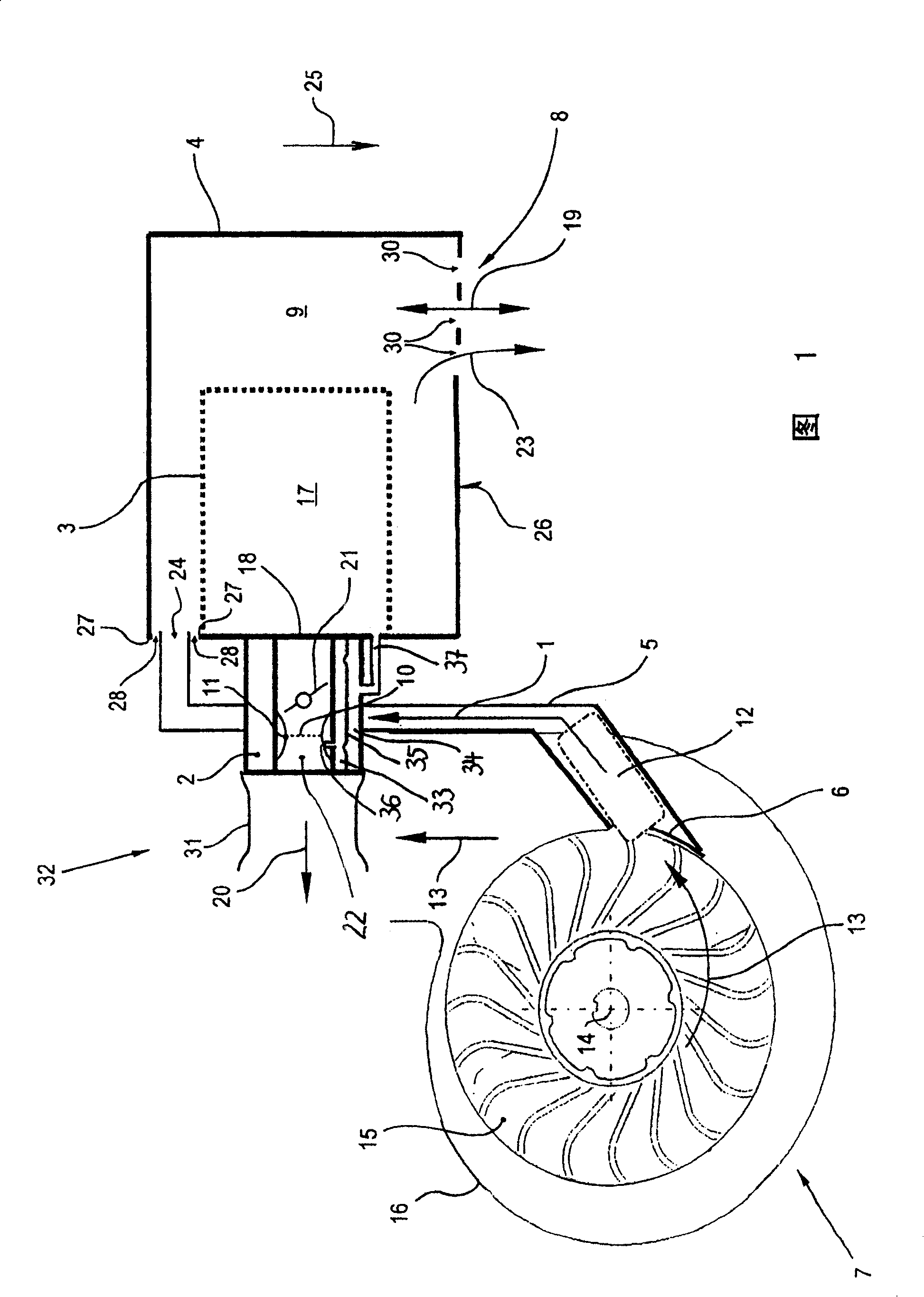
[0022] FIG. 1 schematically shows an exemplary embodiment of the air supply system according to the invention of a hand-held power tool not shown in detail, such as a chainsaw, cutter, suction / blowing tool, etc. FIG. The air intake system shown is used to prepare the combustion air indicated by the arrow 1 for a not shown internal combustion engine for driving a hand-held power tool, and includes a carburetor 2, an air filter upstream of the carburetor 2 Cleaner 3 and a filter box 4 that surrounds air cleaner 3 outside. A vibration gap 32 is formed between the carburetor 2 , which is rigidly mounted on the power tool, and the elastically mounted internal combustion engine, and an elastic coupling 31 is provided for bridging this gap to connect the carburetor 2 to the internal combustion engine.

[0023]The part of the intake system shown is a cooling air fan 7 for cooling the internal combustion engine, in which a combustion air channel 5 leads from an extraction opening 6 in ...


PUM


Abstract

Intake system for supplying combustion air (1) to an internal combustion engine of a hand-held machine tool comprises a compressor (2), and an air filter (3) surrounded by a filter case (4). A combustion air channel (5) leads from a discharge opening (6) in a cooling air fan (7) of the engine to an opening (24) in the filter box. The filter box has at least one defined ventilation opening (8, 28) for connecting an inner chamber (9) of the filter box to the ambient air. The flow cross-section of the ventilation opening is designed so that the air flows through the opening, the intake opening (18) of the compressor and the ventilation opening are balanced at nominal engine speed and a uniform pressure level is set in the inner chamber of the filter box.

Description

technical field [0001] The invention relates to an air intake system for preparing combustion air for an internal combustion engine of a hand-held power tool. Background technique [0002] In hand-held working tools driven by an internal combustion engine, such as chainsaws, cutters, suction / blowers, etc., there is an air intake system for preparing fuel air for the internal combustion engine, in which a carburetor is arranged, which has a front An air filter and a filter box that surrounds the air filter from the outside. The combustion air flow of the internal combustion engine is then sucked in from the interior of the filter box via the carburetor and the upstream air filter. In the known arrangement, a combustion air duct is provided which leads from an intake opening in a cooling air fan of the internal combustion engine to the filter box. Combustion air is diverted from the cooling air flow driven by the cooling air blower by means of the suction holes and is prepar...

Claims


Application Information

Patent Timeline
Patent Type & Authority Patents(China)
IPC IPC(8): F02M35/06F02M35/108F02B33/00F02B63/02
CPCF02B63/02Y10S55/28F02M35/06
Inventor G·迈尔F·基泽维特A·贝纳R·图克尔曼A·克利梅克
Owner ANDREAS STIHL AG & CO KG
Why Eureka
Try Eureka