Ratchet-type tensioner

a tensioner and ratchet-type technology, applied in the direction of belts/chains/gearings, mechanical equipment, belts/chains/gearings, etc., can solve the problems of generating additional noise, reducing the manufacturing cost of parts, and reducing the number of parts and their manufacturing costs, so as to prevent the seizing of the plunger and the reliable prevention of the seizing

Active Publication Date: 2015-06-23
TSUBAKIMOTO CHAIN CO
View PDF7 Cites 2 Cited by
  • Summary
  • Abstract
  • Description
  • Claims
  • Application Information

AI Technical Summary

Benefits of technology

[0019]The bulge of the sliding surfaces of the rack teeth reduces the degree of backlash by reducing the distance between the stop surface and the sliding surface. Thus, it is possible to reduce rattling noise produced by the ratchet mechanism without reducing the pitch of the rack teeth excessively. Furthermore, because the flapping of the flexible transmission medium is suppressed, the flapping noises caused can also be reduced.
[0038]The housing of the tensioner can be attached to an engine having sprockets or other rotating members. The plunger-biasing means can include oil supplied under pressure during operation of the engine to a high-pressure oil chamber formed within the housing. When the first reaction force urging the plunger in the setback direction is generated on starting the engine while the hydraulic pressure within the high-pressure oil chamber is not enough to sustain the first reaction force, the ratchet mechanism can block the setback of the plunger in starting the engine. However, when the second reaction force that sets back the plunger is generated when the tension becomes excessive during operation the engine, the ratchet mechanism allows setback of the plunger, so that it is possible to reduce the excessive tension quickly.

Problems solved by technology

Rattling noise is generated due to abutment of the rack teeth with the ratchet teeth as the plunger advances and sets back, and flapping of the chain also occurs, generating additional noise.
A greater backlash results in greater rattling and flapping noises.
However, due to increased friction between the rack teeth and the ratchet teeth, the plunger can no longer advance as quickly, and cannot follow variations in tension in the chain.
Increasing the tooth depth, however, generates other problems.
In that case, the rattling noise generated when the ratchet teeth are abutted by the rack teeth increases, and the flapping noise of the chain also increases.
This excessive setting back of the plunger, as the ratchet teeth ride over the rack teeth, occurs on starting an engine when there is not enough hydraulic pressure in the high-pressure oil chamber to restricting setback of the plunger, i.e., when the advance-direction biasing force is too small.
There is also a case in which the plunger advances excessively due to looseness or elongation of the chain resulting from fluctuation in tension, or thermal expansion of the engine block or of the chain caused by changes in the temperature of the engine.
When the plunger protrudes excessively, the chain is ultimately placed under excessive tension.
And, if the plunger is restricted from setting back due to the reaction force from the chain when the chain is under excessive tension, the chain travels under excessive load, and generates noise.

Method used


Image

  • Ratchet-type tensioner
  • Ratchet-type tensioner
  • Ratchet-type tensioner

Examples


Embodiment Construction

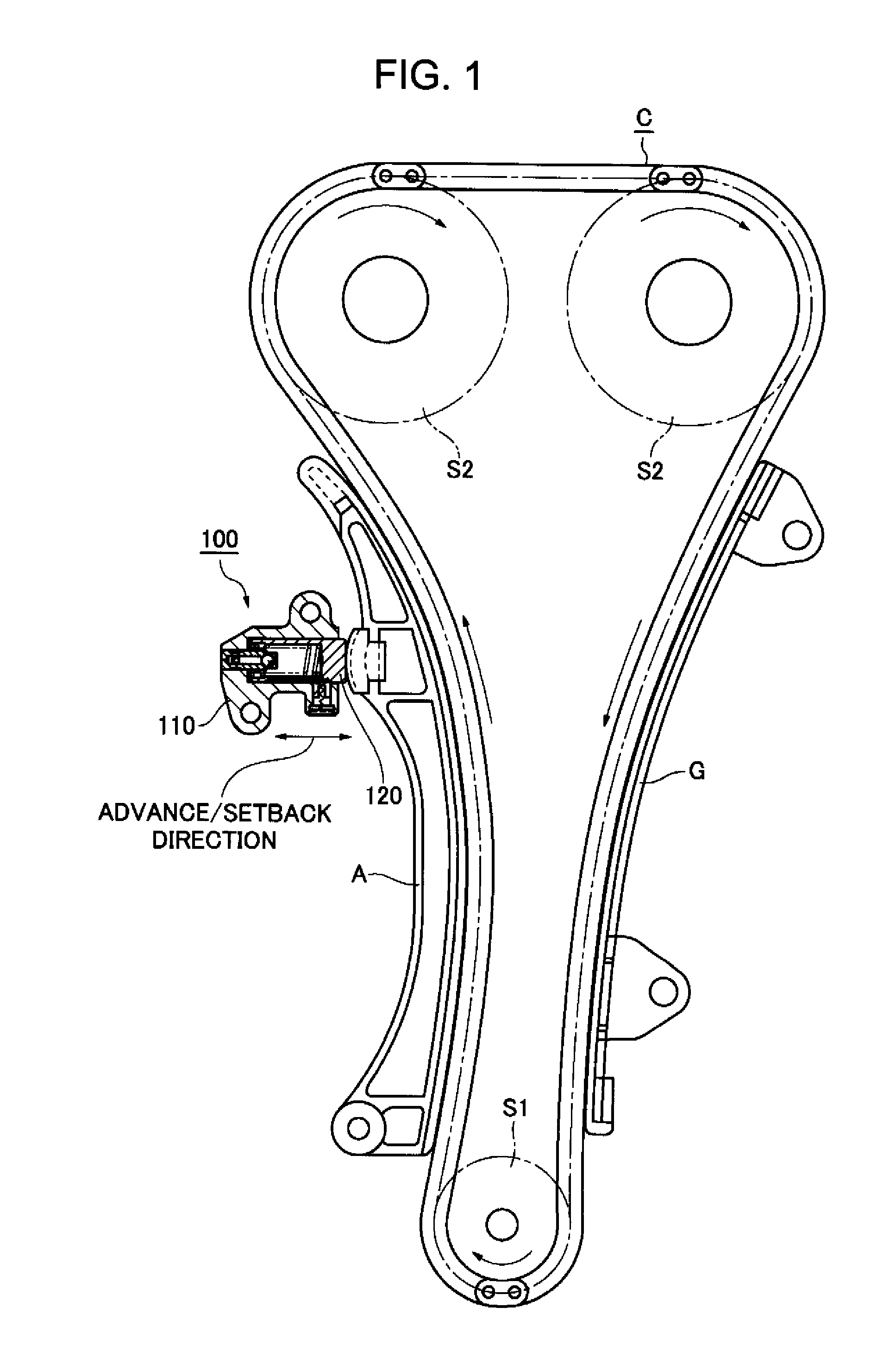
[0050]As shown in FIG. 1, a ratchet-type tensioner 100 is attached to a machine, e.g., an engine not shown, on the slack side of an endless flexible traveling transmission medium in the form of an engine timing chain C. The timing chain is engaged with, and driven by a crankshaft sprocket S1, and engaged with and in driving relationship with a pair of camshaft sprockets S2.

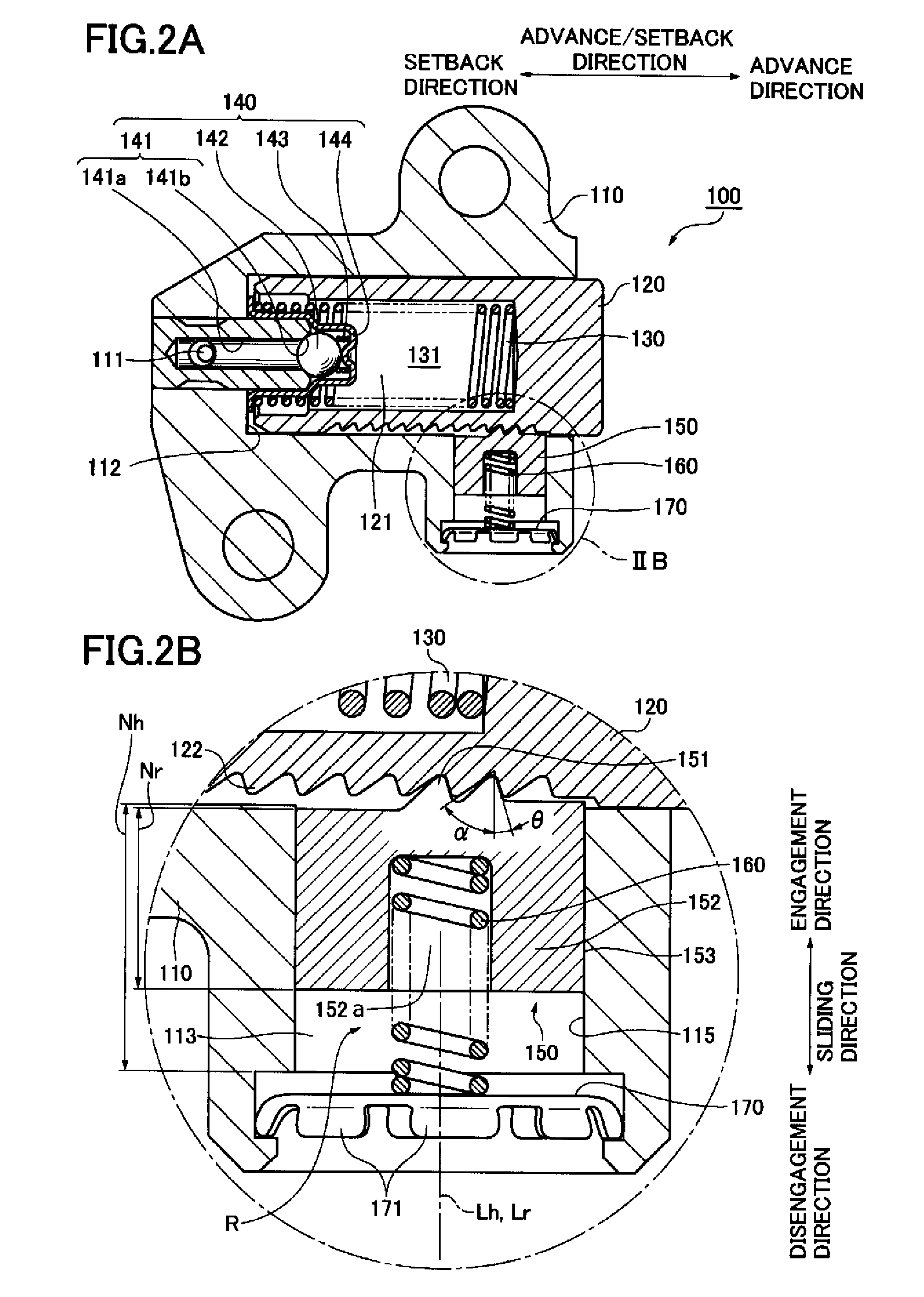
[0051]The ratchet-type tensioner 100 comprises a housing 110, and a plunger 120 that projects out of the housing and is constrained by the housing for movement along an advance / setback direction. The plunger 120 applies tension to the slack side of the timing chain C, i.e., the side that travels from the crankshaft sprocket S1 toward one of the camshaft sprockets S2. The plunger applies tension to the chain through a lever A on which the slack side of the chain slides. The lever is pivoted on the engine block, and presses the plunger 120 at a location remote from the lever's pivot axis.

[0052]A stationary guide G f...


PUM


Abstract

A ratchet-type tensioner, comprising: a housing; a plunger supported by the housing for movement in opposite advancing and setback directions, the plunger having rack teeth provided thereon, and being arranged to advance with respect to the housing along the advancing direction for applying tension to a traveling transmission medium engaged with rotating members; and a ratchet mechanism capable of restricting the plunger from setting back due to a reaction force acting in a setback direction from the transmission medium; said ratchet mechanism comprising: a ratchet-receiving hole provided within the housing; a ratchet element slidable in the ratchet-receiving hole and movable in a sliding direction transverse to the advancing and setback directions; ratchet teeth on the ratchet element engageable with the rack teeth of the plunger; and a ratchet-biasing means for biasing the ratchet element in an engaging direction along the sliding direction so that the ratchet teeth engage with the rack teeth; said ratchet mechanism being capable of restricting the plunger from being set back by a reaction force acting in a setback direction from the transmission medium; said rack teeth having a concave-convex form and being composed of stop surfaces facing in the setback direction and sliding surfaces facing in the advance direction, said sliding surfaces being inclined relative to the sliding direction and facing in a disengaging direction opposite from the engaging direction; each of said sliding surfaces having an entry starting location which the ratchet teeth first engage when starting to enter the rack teeth, and an entry ending location where the engagement of the ratchet teeth with the rack teeth ends; each said sliding surface being a curved surface, all of said curved surface, between said entry starting location and said entry ending location of said sliding surface, bulging in the advancing direction of the plunger and in the disengaging direction of the ratchet element from an imaginary reference plane intersecting said entry starting location and said entry ending location of said sliding surface and perpendicular to another imaginary plane to which the advancing and setback direction of the plunger and the sliding direction of the ratchet element are parallel; and at least a part of said curve midway along said curve between the entry starting location and the entry ending location is convex.

Description

CROSS REFERENCE TO RELATED APPLICATIONS[0001]This application claims priority on the basis of Japanese Patent Application No. 2011-066431, filed on Mar. 24, 2011. The disclosure of Japanese Patent Application No. 2011-066431 is incorporated by reference.FIELD OF THE INVENTION[0002]The invention relates to a ratchet-type tensioner for applying tension to an endless, flexible, transmission medium such as a timing chain for driving one or more camshafts from the crankshaft of an internal combustion engine.BACKGROUND OF THE INVENTION[0003]A typical ratchet-type tensioner includes a plunger slidable in a plunger-accommodating hole in a tensioner housing. The plunger is movable along an advancing and setback direction, and is biased in its advancing, i.e., protruding, direction. The plunger either abuts a flexible transmission medium such as a timing chain directly, or applies tension to the transmission medium through a device such as a pivoted tensioner lever on which the transmission m...

Claims


Application Information

Patent Timeline
Patent Type & Authority Patents(United States)
IPC IPC(8): F16H7/08
CPCF16H7/0848F16H7/08F16H2007/0806F16H2007/0812F16H2007/0853F16H2007/0859
Inventor KUREMATSU, YUJIMORI, KAORIMAEDA, MUNEHIROYOSHIDA, OSAMU
Owner TSUBAKIMOTO CHAIN CO
Why Eureka
Try Eureka