Parallel foamed coaxial cable

a coaxial cable and foaming technology, applied in the direction of cables, power cables, insulated conductors, etc., can solve the problems of affecting the transmission rate, affecting the quality of the cable, so as to reduce the skew, the effect of increasing the transmission rate and high foaming degr

Active Publication Date: 2015-06-23
HITACHI METALS LTD
View PDF6 Cites 11 Cited by
  • Summary
  • Abstract
  • Description
  • Claims
  • Application Information

AI Technical Summary

Benefits of technology

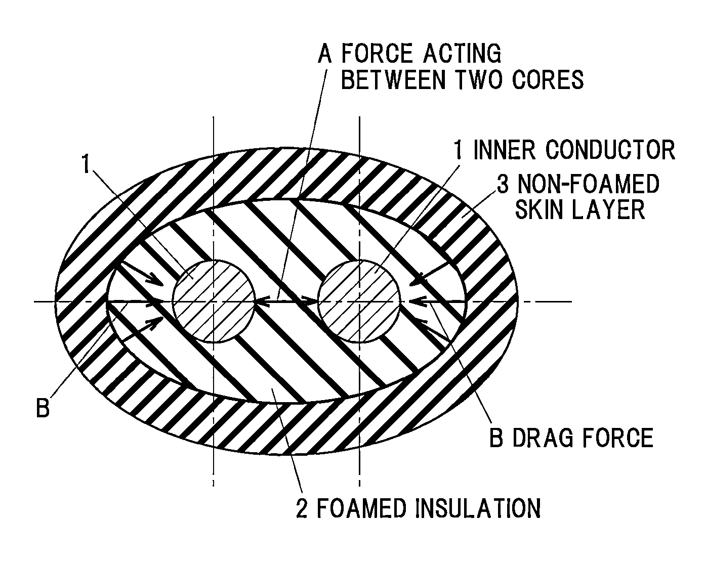
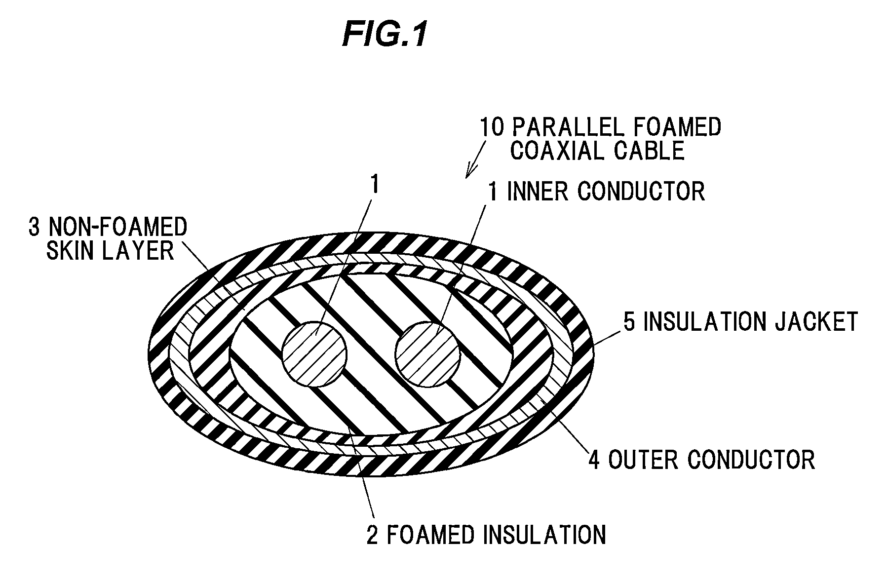
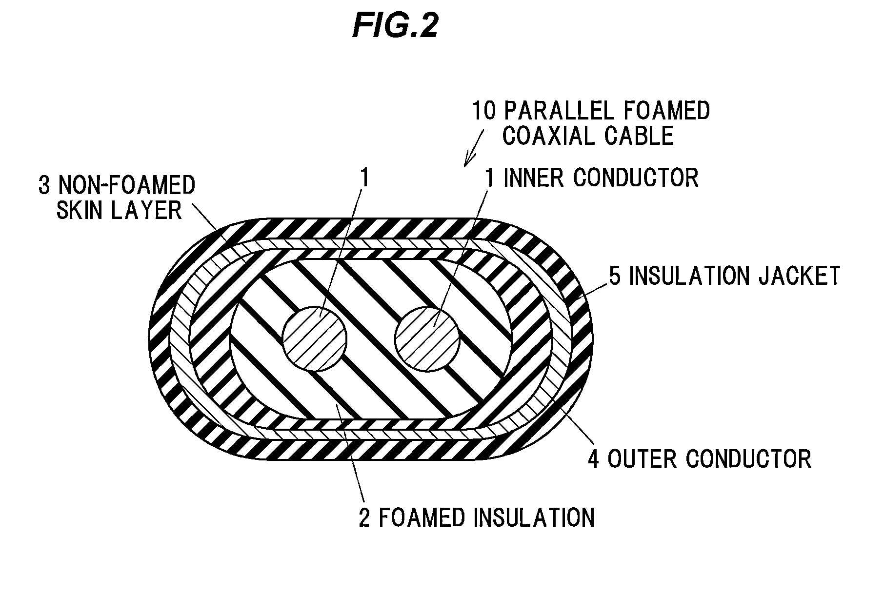
[0025]According to one embodiment of the invention, a parallel foamed coaxial cable can be provided that can simultaneously achieve an increase in transmission rate and a reduction in skew. For example, the parallel foamed coaxial cable is constructed such that a non-foamed skin layer is formed on the foamed insulation with an elliptical shape, a rounded-rectangular shape or a quasi-elliptical shape, and that the thickness distribution (in the cross section) of the non-foamed skin layer is provided to have a maximum thickness in the major axis direction and a minimum thickness in the minor axis direction. Thereby, the parallel foamed coaxial cable can have a high foaming degree of not less than 45% and stabilize the distance between the two cores.

Problems solved by technology

However, the position in the parallel direction of the two cores may be unstable, which causes adverse effect on impedance.
This can impede the improvement in delay time.
However, the increase in the cable diameter may cause an increase in the size of a connector device or a need to redesign a substrate thereof, thus an increase in manufacturing cost.
However, if the non-foamed skin layer 3 is constantly too thin, the drag force may not act sufficiently even though high foaming of the entire insulation can be achieved.
Thus, it is likely to deform when receiving an expansion force or an external force in the process of foaming, so that the position of two cores in the parallel direction becomes unstable.

Method used


Image

  • Parallel foamed coaxial cable
  • Parallel foamed coaxial cable
  • Parallel foamed coaxial cable

Examples


example 1

[0086]The constituent materials shown in Table 1 were used. That is, a silver-plated copper wire (product name: 24AWG (0.511 mm in diameter), from Sanshu-Densen KK) was used as an inner conductor, 50 parts by mass of high-density polyethylene (product name: 6944, from Dow Chemical Co.), 50 parts by mass of low-density polyethylene (product name: B028, from Ube Industries, Ltd.) and 1 part by mass of nucleating agent (product name: ADCA, from Eiwa Chemical Ind. Co., Ltd.) were used as the foamed insulation, high-density polyethylene (product name: 6944, from Dow Chemical Co.) was used as the non-foamed skin layer and a copper tape (15 μm in thickness, including 6 μm of PET) was used as an outer conductor.

[0087]The extrusion conditions are shown in Table 2. That is, when a foamed insulation was made by a chemical foaming method at a screw speed fixed at 20 rpm and a cylinder temperature fixed at 220° C. (without gas injection), a foamed insulation having the foaming degree of about 55...


PUM

PropertyMeasurementUnit
impedanceaaaaaaaaaa
impedanceaaaaaaaaaa
impedanceaaaaaaaaaa

Abstract

A parallel foamed coaxial cable includes one or more pairs of inner conductors aligned in parallel, a foamed insulation covering together the inner conductors and having a cross sectional shape including an elliptical shape, a rounded-rectangular shape or a quasi-elliptical shape formed by combining a plurality of curved lines, a non-foamed skin layer covering the foamed insulation and having a maximum thickness in a major axis direction of the cross sectional shape of the foamed insulation and a minimum thickness in a minor axis direction of the cross sectional shape of the foamed insulation, an outer conductor covering the non-foamed skin layer, and an insulation jacket covering the outer conductor. The maximum thickness of the non-foamed skin layer is not less than 1% of a major axis of the cross sectional shape of the foamed insulation.

Description

[0001]The present application is based on Japanese patent application No. 2012-006840 filed on Jan. 17, 2012, the entire contents of which are incorporated herein by reference.BACKGROUND OF THE INVENTION[0002]1. Field of the Invention[0003]The invention relates to a parallel foamed coaxial cable and, in particular, a parallel foamed coaxial cable used in electronic devices such as computers.[0004]2. Description of the Related Art[0005]According to the increase in data transmission speed of electronic devices such as computers, cables used therein need to be adapted to a higher transmission rate. For example, in the application for differential transmission, as shown in FIG. 10, a two-core parallel cable is known as a conventional cable to meet such a need in which two insulated core wires 26 are arranged in parallel which are each formed by covering an inner conductor 21 with a foamed insulation 22 to have a circular cross section, an outer conductor 24 is disposed therearound, and ...

Claims


Application Information

Patent Timeline
Patent Type & Authority Patents(United States)
IPC IPC(8): H01B7/18H01B11/18H01B11/20
CPCH01B11/1882H01B11/20
Inventor KODAMA, SOHEIKAGA, MASAFUMINAKAYAMA, AKINARI
Owner HITACHI METALS LTD
Why Eureka
Try Eureka