Inductively powered mobile sensor system

a mobile sensor and inductive supply technology, applied in the field of inductive supply of power to mobile sensors, can solve the problems of potential source of infection, introduction of movement artefacts, and method has a number of undesirable limitations

Active Publication Date: 2015-06-23
AUCKLAND UNISERVICES LTD
View PDF28 Cites 12 Cited by
  • Summary
  • Abstract
  • Description
  • Claims
  • Application Information

AI Technical Summary

Problems solved by technology

This method has a number of undesirable limitations, some of which include: the introduction of movement artefacts; restraints of movement exacerbating an unnatural environment; a potential source of infection, and; reliability problems with wires becoming tangled, breaking, or being bitten.
Some systems presently exist for the wireless monitoring of animals, however these systems have power management problems.
The battery is often bulky which can cause difficulties when providing the sensor unit within the animal.
Also, there is an inability to remotely undertake long term recordings of physiological parameters because the batteries need to be removed so that they may be replaced or recharged.
Wireless supply of power to biosensors has been attempted, but these systems either require a tightly controlled coupling between the biosensor and power source, or can only supply sufficient power for monitoring slowly changing parameters, such as temperature.
Controlling the power transferred to the sensor can be difficult because the power available varies depending on location and orientation of the sensor with respect to the power source.
This is obviously highly undesirable causing discomfort or harm to the animal in which the sensor has been implanted, and exacerbating an unnatural environment for the animal.
However, this does not address problems with heat dissipation.
Thus, the problems of variable distance and random orientation of implants in relation to the primary coils are not addressed.

Method used


Image

  • Inductively powered mobile sensor system
  • Inductively powered mobile sensor system
  • Inductively powered mobile sensor system

Examples


Embodiment Construction

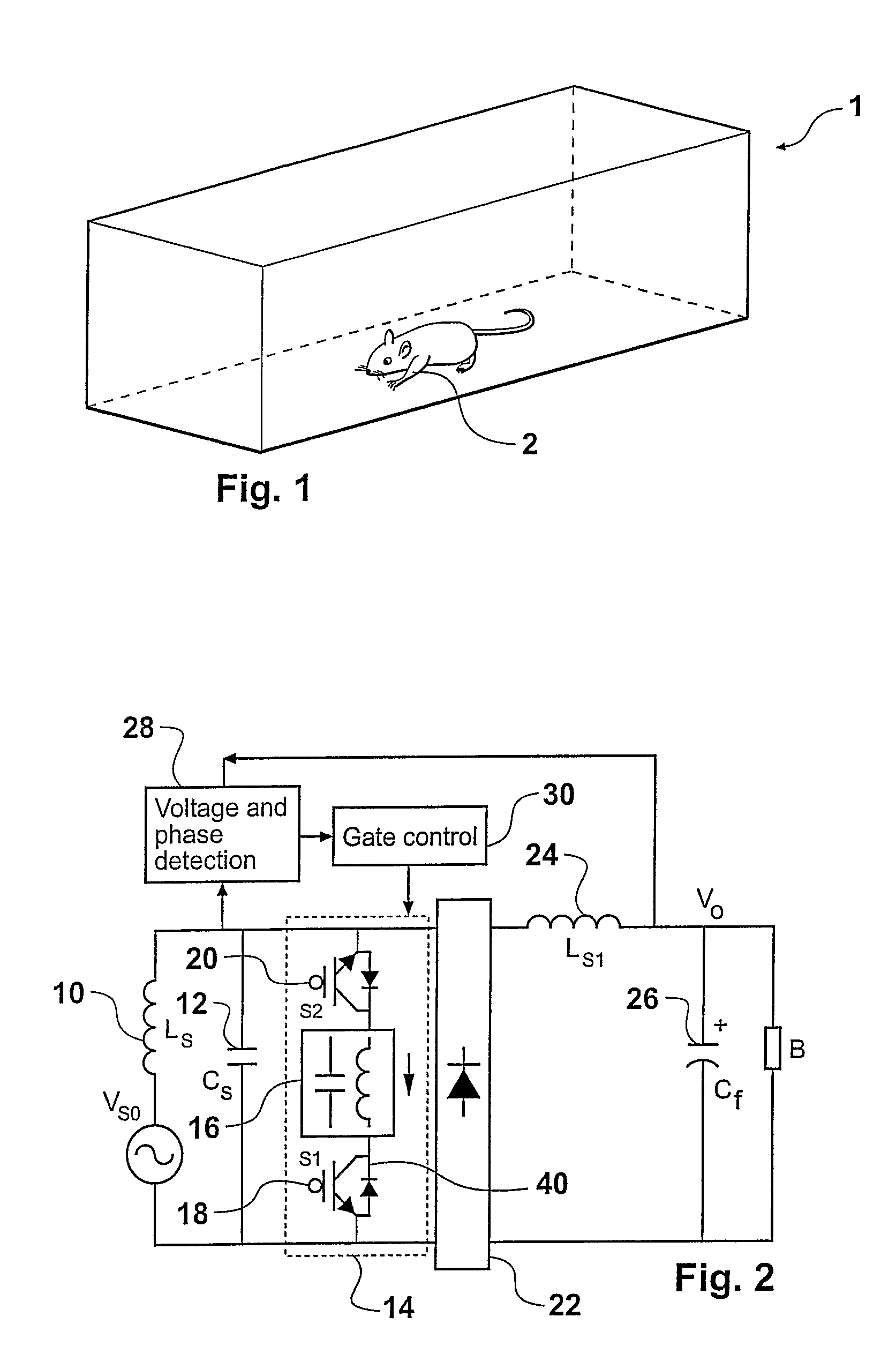
[0093]Referring to FIG. 1, an enclosure in the form of an animal cage is shown generally referenced 1 containing an animal such as a mouse 2. Although the invention will be described with reference to a cage suitable for containing a small animal such as a mouse, those skilled in the art will appreciate that the invention is generally applicable to the wireless supply of power to a very wide range of animals (including humans or other living creatures) within a defined space. Furthermore, although the invention is described below in relation to biosensors, those skilled in the art will realise that the invention is applicable to other sensors.

[0094]An electromagnetic field may be established in the space defined by the enclosure by providing an alternating current in a primary conductor adjacent to the cage 1. Electrical energy may be transferred from the field to a tuned inductive pick-up circuit implanted in the animal 2. The pick-up circuit can thus provide the power supply requi...


PUM


Abstract

The present invention provides an inductively powered sensor system having a primary conductive path capable of being energized to provide an electromagnetic field in a defined space. An inductive power pick-up is associated with a sensor and is capable of receiving power from the field to supply the sensor. The system includes a first sensing unit to sense the power available to the pick-up and a control unit to increase or decrease the power available to the sensor dependant on the sensed power available. A method of inductively powering a sensor, an inductively powered sensor and an animal enclosure including one or more primary conductive path of an inductive power supply are also disclosed.

Description

CROSS-REFERENCE TO RELATED APPLICATIONS[0001]This is a U.S. National Phase application under 35 U.S.C. 371 of International Patent Application No. PCT / NZ2005 / 000245, filed on Sep. 16, 2005, which claims priority to New Zealand Patent Application No. 535390, filed on Sep. 16, 2004. The International Application was published on Mar. 23, 2006 as WO 2006 / 031133 A1 under PCT Article 21(2).FIELD OF THE INVENTION[0002]This invention relates to inductive supply of power to mobile sensors. The invention has particular application to a wireless power supply for biosensors that are implanted in living creatures (including humans) and transmit data representative of the physiological parameters to a receiver through a wireless link.BACKGROUND[0003]Physiological parameters in animals are measured using sensors which are placed near, on or under the skin. Wires then carry the signal from the sensor to an external amplifier and display unit. This method has a number of undesirable limitations, so...

Claims


Application Information

Patent Timeline
Patent Type & Authority Patents(United States)
IPC IPC(8): H02J17/00H02J5/00A61B5/00
CPCH02J5/005A61B5/0002A61B2560/0219A01K1/031A01K11/006H02J50/10H02J50/402H02J2310/23H02J7/025H01F38/14A61B5/24H02J50/90H02J50/12
Inventor MALPAS, SIMON CHARLESHU, AIGUOBUDGETT, DAVID
Owner AUCKLAND UNISERVICES LTD
Why Eureka
Try Eureka