
Low energy wireless proximity pairing

a low-energy, wireless technology, applied in the field of low-energy wireless proximity pairing, to achieve the effect of avoiding such undesired pairing, reducing power consumption, and ensuring security and/or privacy

Inactive Publication Date: 2015-06-23
BOSE CORP
View PDF4 Cites 10 Cited by
  • Summary
  • Abstract
  • Description
  • Claims
  • Application Information

AI Technical Summary

Benefits of technology

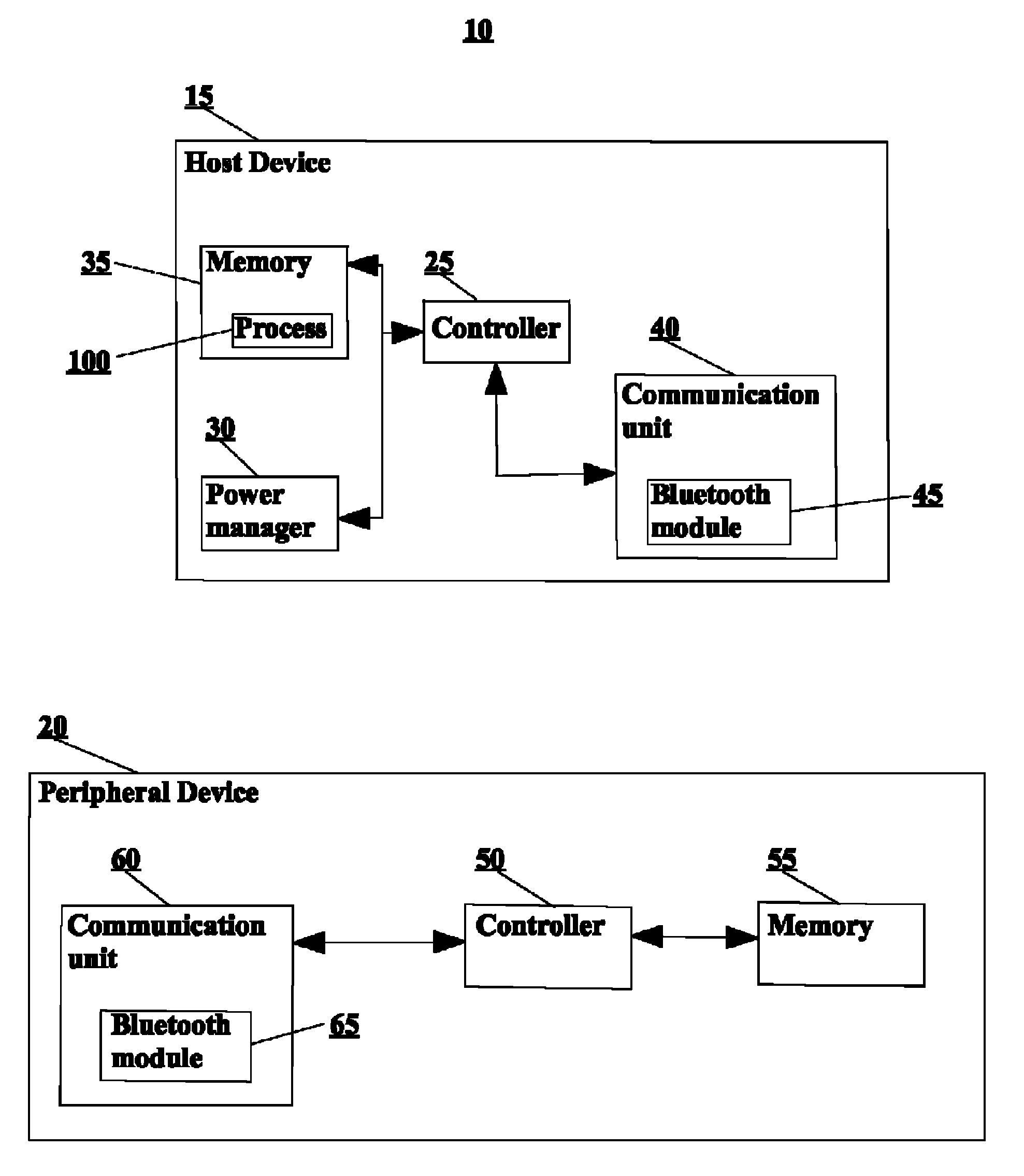
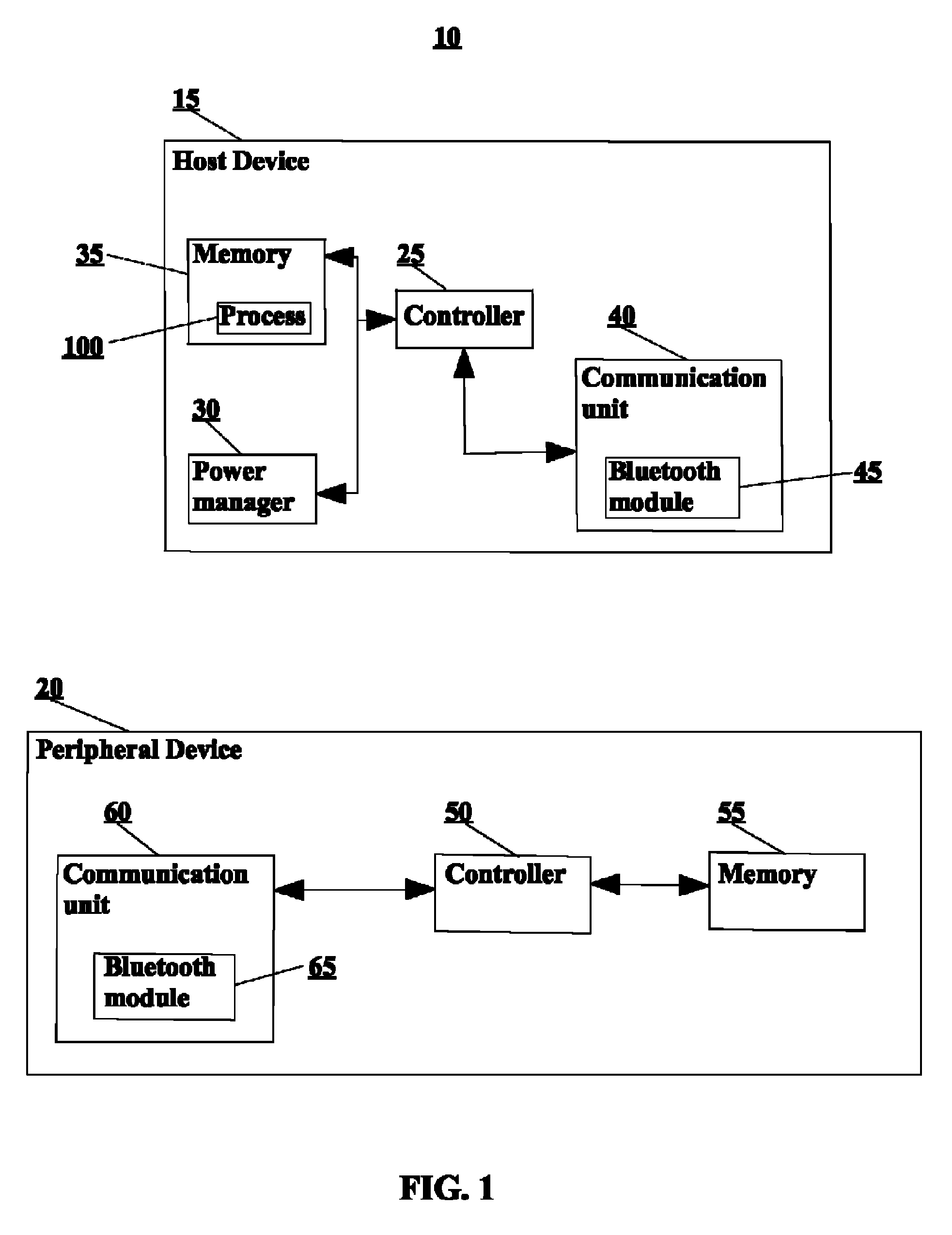
[0004]In a general aspect, an approach disclosed herein provides a way of pairing (e.g., establishing a wireless communication link between) a peripheral with a host device without requiring manual intervention to initiate or establish a pairing mode and / or limiting potential unintended pairing with distant host devices. By limiting initiation of pairing to situations in which the peripheral is in proximity of (e.g., directly adjacent to, within 2 cm of) the host undesired pairing with other hosts is avoided. The requirement for proximity to initiate pairing further provides a degree of security and / or privacy by avoiding such undesired pairing. Furthermore, by requiring proximity of the peripheral device and host device, substantially lower power is needed for the broadcasts by the peripheral than if longer-distance pairing was enabled, thereby conserving power (e.g., in a battery powered peripheral) and potentially reducing radio interference caused by the peripheral. In some examples, the peripheral further reduces power consumption and inadvertent pairing by limiting broadcasts according to particular operating modes, for instance, in an initial power-up mode extending from power-up by a fixed time duration. Lastly, pairing based upon proximity appeals to physical intuition of the end user, resulting in a better user experience.

Problems solved by technology

Furthermore, by requiring proximity of the peripheral device and host device, substantially lower power is needed for the broadcasts by the peripheral than if longer-distance pairing was enabled, thereby conserving power (e.g., in a battery powered peripheral) and potentially reducing radio interference caused by the peripheral.

Method used


Image

  • Low energy wireless proximity pairing
  • Low energy wireless proximity pairing
  • Low energy wireless proximity pairing

Examples


Embodiment Construction

[0019]The subject innovation is now described with reference to the drawings, wherein like reference numerals are used to refer to like elements throughout. In the following description, for purposes of explanation, numerous specific details are set forth in order to provide a thorough understanding of the present invention. It may be evident, however, that the present invention may be practiced without these specific details. In other instances, well-known structures and devices are shown in block diagram form in order to facilitate describing the present invention.

[0020]As used in this application, the term “or” is intended to mean an inclusive “or” rather than an exclusive “or.” That is, unless specified otherwise, or clear from context, “X employs A or B” is intended to mean any of the natural inclusive permutations. That is, if X employs A, X employs B, or X employs both A and B, then “X employs A or B” is satisfied under any of the foregoing instances. Moreover, articles “a” a...


PUM


Abstract

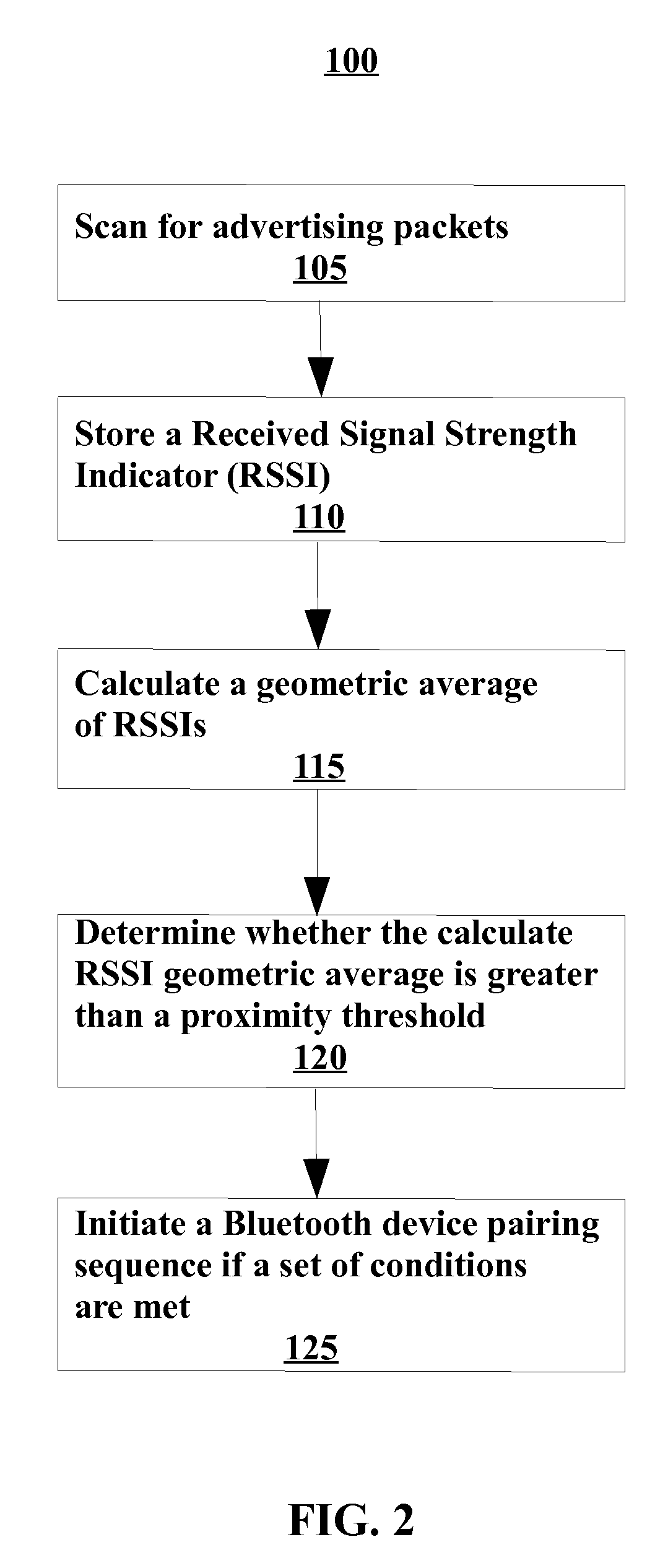
A method of pairing devices includes causing a Bluetooth-enabled host device and a Bluetooth-enabled peripheral device to be located proximate to each other, the Bluetooth-enabled host device comprising at least a processor, a memory and an antenna, in the Bluetooth-enabled host device, detecting advertising packets broadcast by the Bluetooth-enabled peripheral device on one or more of a plurality of advertising channels, saving a numeric indicator of each of multiple detected advertising packets, determining an average numeric indicator from the saved numeric indicators of each of the separately detected advertising packets, if the average numeric indicator exceeds a proximity threshold, determining whether a set of conditions are met, and initiating a Bluetooth device pairing sequence between the Bluetooth-enabled host device and the Bluetooth-enabled peripheral device if the set of conditions are met.

Description

BACKGROUND OF THE INVENTION[0001]The present invention relates to wireless technology, and more specifically to a low energy wireless proximity pairing.[0002]In general, Bluetooth wireless technology is a wireless communications system intended to replace the cables connecting electronic devices. Bluetooth low energy wireless technology includes ultra-low peak, average and idle power consumption, an ability to run for years on standard coin-cell batteries, low cost, multi-vendor interoperability and enhanced range. Reduced power consumption means longer battery life. Bluetooth is the link normally used to transport signals in operation, for example audio signals. Bluetooth LE is normally used to transport short pieces of information, for example telemetry signals. Bluetooth and Bluetooth LE use different radios; we refer to a device having both Bluetooth and Bluetooth LE radios as Bluetooth-enabled. In order for two devices to communicate over Bluetooth, they must first be paired. A...

Claims


Application Information

Patent Timeline
Patent Type & Authority Patents(United States)
IPC IPC(8): H04B7/00H04W52/02H04W4/00H04W76/02H04W4/80
CPCH04W76/023H04W4/008H04W52/0245G08C2201/12G08C2201/20G08C2201/91H04W4/80H04W76/14Y02D30/70
Inventor LIU, PETER T.
Owner BOSE CORP
Learn More