
Apparatus and method for removing materials from a material collection container

a technology for removing materials and material collection containers, which is applied in the direction of separation processes, transportation and packaging, and feed/displacement of settling tanks, etc. it can solve the problems of inability to collect sludge in one of the two header pipes, affecting the movement of the larger conduit, and affecting the quality of the material collected

Active Publication Date: 2015-06-30
ROBERTS MARKETING DE
View PDF23 Cites 17 Cited by
  • Summary
  • Abstract
  • Description
  • Claims
  • Application Information

AI Technical Summary

Benefits of technology

This patent is about a material removal system that can efficiently and effectively remove material from a collection container. The system includes a first and second telescoping conduits, with the first conduit being movable relative to the second conduit. A header is connected to the first conduit and can be placed close to the floor of the collection container. The system is cost-effective, easy to install and operate, and includes a support assembly that allows for the movement of collection components in all parts of the container. The materials can be efficiently removed using the material removal system.

Problems solved by technology

However, these systems have inherent disadvantages due to their designs.
The movement of the larger conduit is impeded by the sludge accumulated in the lower portion of the detention basin or collection container, due to the position of the telescoping conduits relative to the removal headers and the sludge accumulating in the detention basin or collection area.
Further, there is no means by which sludge can be collected in one of the two header pipes independent of the other header pipe.
Moreover, the proximity of the two header pipes to the floor of the detention basin or collection container is limited by the size of the diameter of the larger conduit as the longitudinal axis of the two header pipes intersects the longitudinal axis of the larger conduit of the two telescoping conduits.

Method used


Image

  • Apparatus and method for removing materials from a material collection container
  • Apparatus and method for removing materials from a material collection container
  • Apparatus and method for removing materials from a material collection container

Examples


Embodiment Construction

[0048]The preferred forms of the invention will now be described with reference to FIGS. 1-22. The appended claims are not limited to the preferred forms and no term and / or phrase used herein is to be given a meaning other than its ordinary meaning unless it is expressly stated otherwise.

FIGS. 1 Through 7

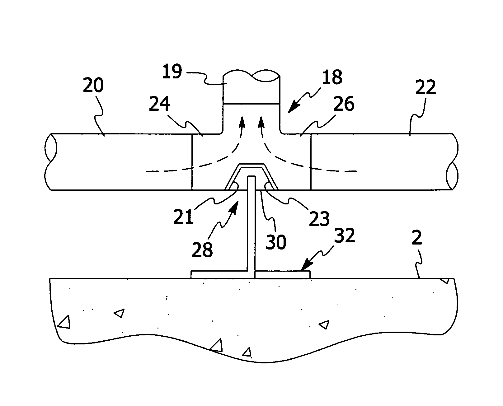
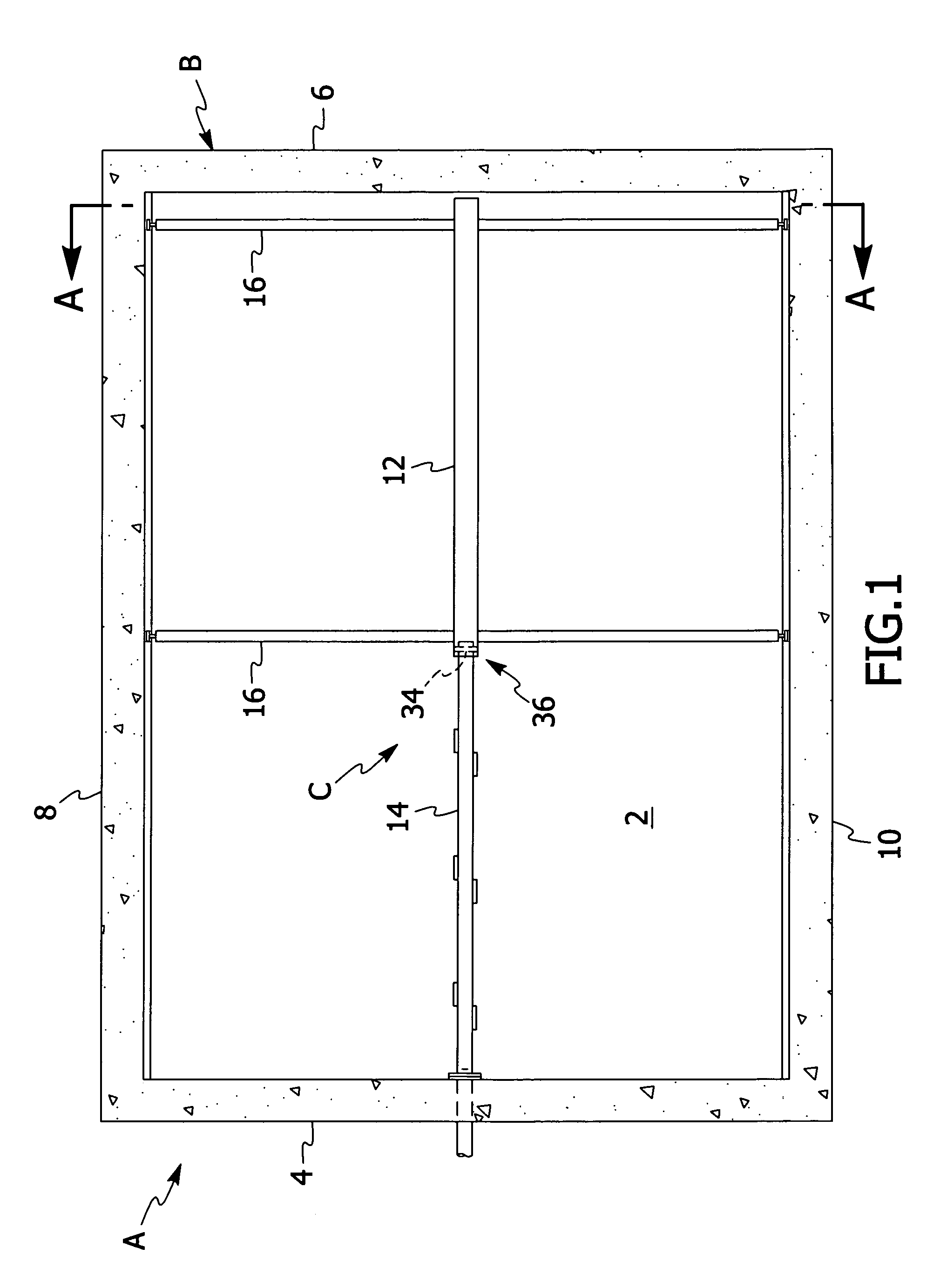
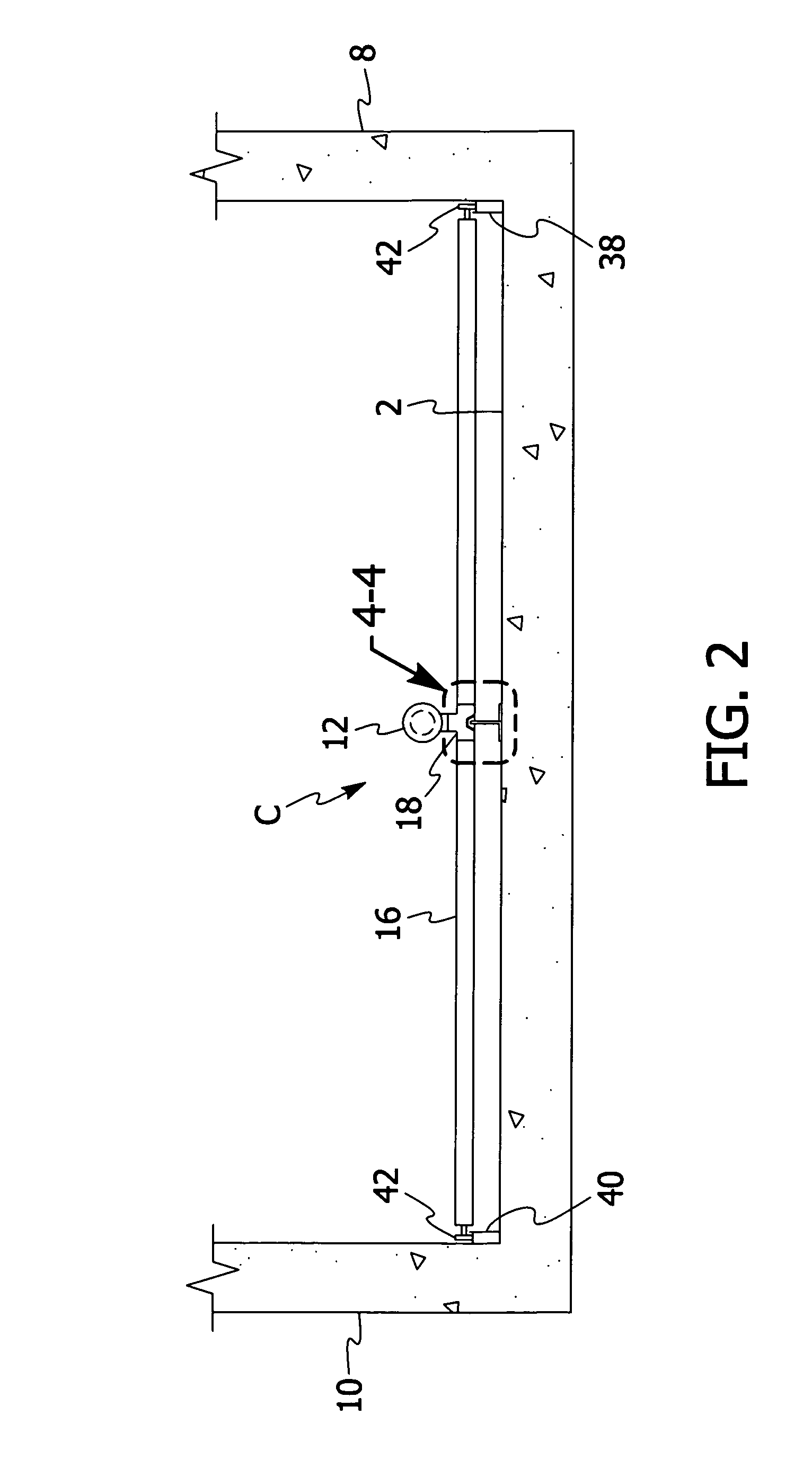
[0049]Referring to FIGS. 1 to 3, a settling system A employing a preferred form of the invention is illustrated in one of many possible configurations. In the most preferred form, the material being removed from the settling system A is sludge. Settling system A includes a material container B. The material container may include one or more settling assemblies (not shown) having a plurality of inclined passageways in which an influent to be filtered or clarified is passed. The plurality of inclined passageways may be formed for example by a plurality of plates or tubes. As the influent passes through the inclined passageways of the one or more settling assemblies impurities in the i...


PUM

PropertyMeasurementUnit
frictionaaaaaaaaaa
structuresaaaaaaaaaa
surface areaaaaaaaaaaa

Abstract

An apparatus for removing material collected in a material collection container having a floor and at least one substantially vertically extending wall. The apparatus includes a material removal assembly for removing material collected in the material collection container. The material removal assembly includes a first conduit and a second conduit. The first conduit is in telescoping relationship with the second conduit to permit the first conduit to move relative to the second conduit. The first conduit and the second conduit each have a longitudinal axis. The material removal assembly further includes at least one material removal header configured to receive material accumulating on the floor of the material collection container. The material removal assembly is preferably configured to enhance numerous aspects of the sludge removal process.

Description

FIELD OF THE INVENTION[0001]The present invention is directed to an apparatus and method for removing material from a material collection container. The material may be any form of impurity including a fluid, a solid or a combination thereof. In the most preferred form, the present invention is directed to an apparatus and method for removing sludge from a sludge collection container. The sludge collection container may include one or more members designed to settle sludge from water or wastewater including but not limited to settling plates or settling tubes. The present invention may be used in containers having other structures that would intentionally or inadvertently cause impurities to collect in the containers and where it is beneficial to remove the collected impurities from the containers.BACKGROUND OF THE INVENTION[0002]Filter or clarification systems have employed various devices to remove impurities from water and / or wastewater for a number of years. In these types of fi...

Claims


Application Information

Patent Timeline
Patent Type & Authority Patents(United States)
IPC IPC(8): B01D21/18B65D88/54B01D21/00B01D21/24B01D21/20C02F1/00
CPCB65D88/548B01D21/18B01D21/0003B01D21/0024B01D21/20B01D21/245Y10T137/8593C02F2001/007B01D21/34
Inventor ROBERTS, R. LEEBATTAGLIA, MARK ROBERTADDISON, MARK KEVINPASKMAN, DAVID STUARTTAYLOR, ANDREW SCOTT
Owner ROBERTS MARKETING DE
Learn More