
Strain sensors, methods of making same, and applications of same

a technology of strain sensor and strain gage, which is applied in the field of strain sensor, can solve the problems of high failure rate of traditional strain gage, and inability to drift, and achieve the effect of increasing the electrical conductivity

Inactive Publication Date: 2015-06-30
THE BOARD OF TRUSTEES OF THE UNIV OF ARKANSAS
View PDF21 Cites 6 Cited by
  • Summary
  • Abstract
  • Description
  • Claims
  • Application Information

AI Technical Summary

Benefits of technology

This patent text describes a method to increase the electrical conductivity of carbon nanotubes by functionalizing their surfaces. This can be useful in various applications where increased electrical conductivity is needed.

Problems solved by technology

However, during development of composite cryogenic tanks, there have been a couple of incidents involving dramatic tank failure during testing [3, 4].
Current structural monitoring technologies typically use metal foil strain gauges but which have significant limitations such as measuring strain in designated directions and locations, and are susceptible to drifting due to temperature sensitivity.
Also, traditional strain gages have an extremely high failure rate and therefore are not well suited for long term use to determine the “health” of a composite structure.
Furthermore, many structures such as airframes and cryogenic tanks do not allow access to place or change strain gages if failed.
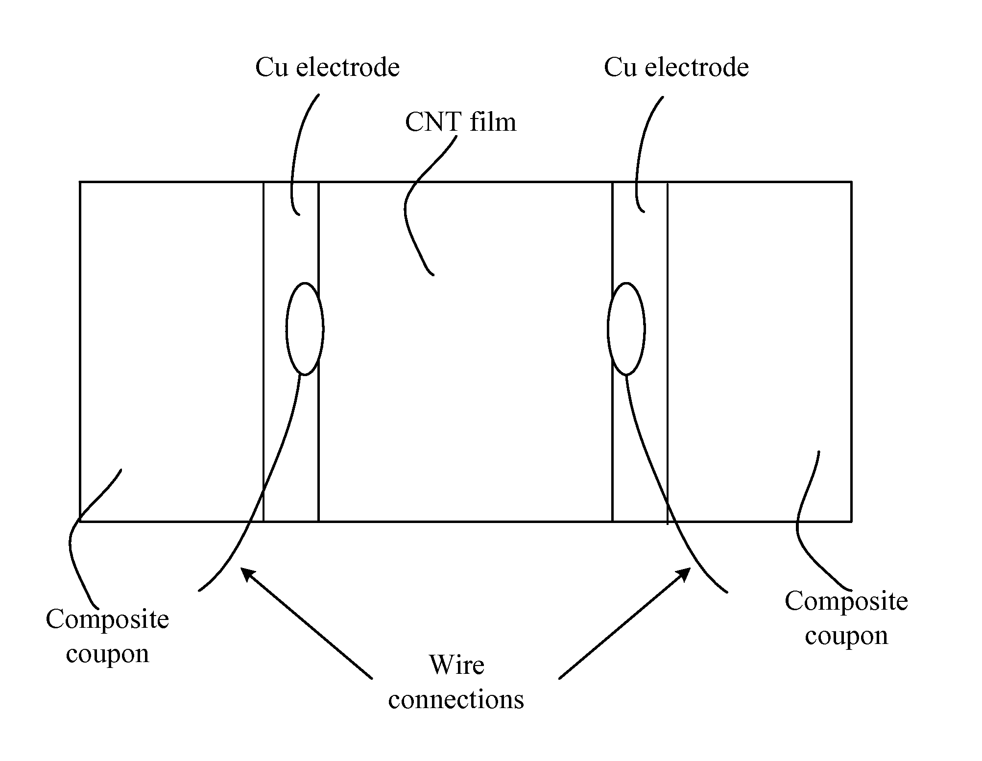
The use of CNT films for strain sensors for structural health monitoring has been proposed and tested [10-14] with excellent results, however in these cases, no specific applications were addressed.

Method used


Image

  • Strain sensors, methods of making same, and applications of same
  • Strain sensors, methods of making same, and applications of same
  • Strain sensors, methods of making same, and applications of same

Examples


Embodiment Construction

[0046]The present invention is more particularly described in the following examples that are intended as illustrative only since numerous modifications and variations therein will be apparent to those skilled in the art. Various embodiments of the invention are now described in detail. Referring to the drawings, like numbers indicate like components throughout the views. As used in the description herein and throughout the claims that follow, the meaning of “a”, “an”, and “the” includes plural reference unless the context clearly dictates otherwise. Also, as used in the description herein and throughout the claims that follow, the meaning of “in” includes “in” and “on” unless the context clearly dictates otherwise. Moreover, titles or subtitles may be used in the specification for the convenience of a reader, which shall have no influence on the scope of the present invention. Additionally, some terms used in this specification are more specifically defined below.

DEFINITIONS

[0047]T...


PUM

PropertyMeasurementUnit
lengthsaaaaaaaaaa
outer diametersaaaaaaaaaa
temperatureaaaaaaaaaa

Abstract

In one aspect, the present invention relates to a layered structure usable in a strain sensor. In one embodiment, the layered structure has a substrate with a first surface and an opposite, second surface defining a body portion therebetween; and a film of carbon nanotubes deposited on the first surface of the substrate, wherein the film of carbon nanotubes is conductive and characterized with an electrical resistance. In one embodiment, the carbon nanotubes are aligned in a preferential direction. In one embodiment, the carbon nanotubes are formed in a yarn such that any mechanical stress increases their electrical response. In one embodiment, the carbon nanotubes are incorporated into a polymeric scaffold that is attached to the surface of the substrate. In one embodiment, the surfaces of the carbon nanotubes are functionalized such that its electrical conductivity is increased.

Description

CROSS-REFERENCE TO RELATED PATENT APPLICATION[0001]This application claims priority to and the benefit of, pursuant to 35 U.S.C. §119(e), U.S. provisional patent application Ser. No. 61 / 552,849, filed Oct. 28, 2011, entitled “STRAIN SENSORS WITH CARBON NANOTUBE COATINGS, METHODS OF MAKING SAME, AND APPLICATIONS OF SAME”, by Alexandru S. Biris et al., which is incorporated herein in its entirety by reference.[0002]Some references, which may include patents, patent applications and various publications, are cited and discussed in the description of this invention. The citation and / or discussion of such references is provided merely to clarify the description of the present invention and is not an admission that any such reference is “prior art” to the invention described herein. All references cited and discussed in this specification are incorporated herein by reference in their entireties and to the same extent as if each reference was individually incorporated by reference. In term...

Claims


Application Information

Patent Timeline
Patent Type & Authority Patents(United States)
IPC IPC(8): D01F9/127B82Y30/00G01B7/16H01B1/04B82Y40/00
CPCD01F9/127B82Y30/00G01B7/18H01B1/04Y10T428/25Y10T428/30B82Y40/00Y10T428/249921
Inventor BIRIS, ALEXANDRU S.TRIGWELL, STEVENHATFIELD, WALTER
Owner THE BOARD OF TRUSTEES OF THE UNIV OF ARKANSAS
Learn More