Sheet manufacturing apparatus and sheet manufacturing method

a technology of sheet manufacturing and manufacturing method, which is applied in the direction of papermaking, textiles and paper, press section, etc., can solve the problem of damage to the separation layer

Inactive Publication Date: 2015-07-07
SEIKO EPSON CORP
View PDF13 Cites 14 Cited by
  • Summary
  • Abstract
  • Description
  • Claims
  • Application Information

AI Technical Summary

Benefits of technology

[0011]According to this configuration, since the pressurizing force from the heating rollers on the downstream side larger than the pressurizing force from the heating rollers on the upstream side, it is possible to suppress stretching of the web by gradually pressurizing and heating the web over a plurality of times.
[0013]According to this configuration, it is possible to easily configure the separation layer which does not become attached to the web by including fluorine.
[0015]It is easy for a front end portion of the web to be wound around the pressurizing and heating unit since the front end portion of the web is not pressed down. Since, in a configuration where the web with a continuous form becomes webs with sheet shapes due to the cutting unit, front end portions are generated for each of the sheet shapes, the effect is particularly exhibited in this configuration.
[0017]According to this configuration, the web is first pressurized by the first pressurizing unit which is arranged on the upstream side and is then pressurized by the second pressurizing unit which is arranged on the downstream side. Here, the first pressurizing unit pressurizes while heating. In addition, due to the first pressurizing unit having the separation layer, it is possible for the web to be transferred without becoming attached to the first pressurizing unit even if the web is heated and pressurized. Furthermore, since the pressurizing force with regard to the web from the first pressurizing unit is smaller than the pressurizing force from the second pressurizing unit, the durability of the separation layer is improved. Then, the pressurizing force from the second pressurizing unit on the downstream side is larger than the pressurizing force from the first pressurizing unit and insufficient pressurizing by the first pressurizing unit is compensated for by the second pressurizing unit. In addition, it is possible for there to be no separation layer on the second pressurizing unit since the web does not become adhered to the second pressurizing unit due to no heating being carried out. It is possible for high pressures to be endured since there is no separation layer.
[0019]According to this configuration, it is possible for the web to be thin by reliability bonding and pressurizing resin and fibers by cooling the web by the temperature of the web remaining in a state of being high to a certain extent due to the first pressurizing unit and the web being passed through the second pressurizing unit without heating in a state where resin is melted.

Problems solved by technology

Here, there is a problem in that the transfer medium becomes attached to a heating and pressurizing unit when the transfer medium is heated and pressurized.
Since the durability of such a separation layer is low with regard to high pressures, there is a problem in that the separation layer is damaged when repetitively performing heating and pressurizing of the transfer medium at high pressures.

Method used


Image

  • Sheet manufacturing apparatus and sheet manufacturing method
  • Sheet manufacturing apparatus and sheet manufacturing method
  • Sheet manufacturing apparatus and sheet manufacturing method

Examples


modified example 1

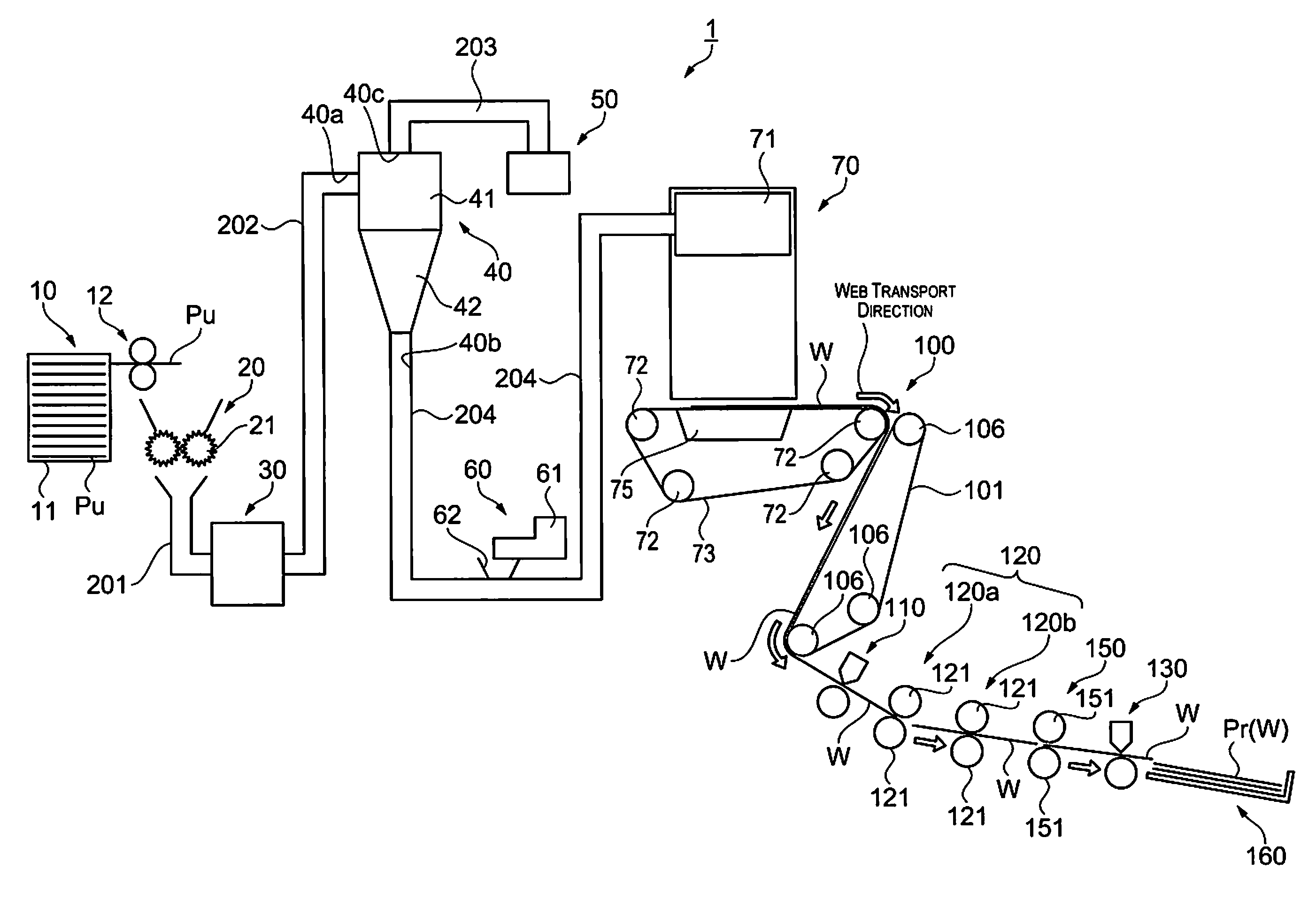
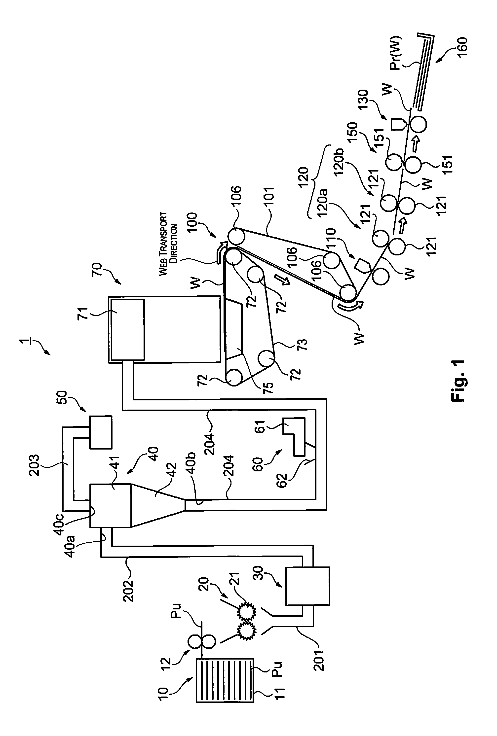
[0051]There is a configuration in the embodiment described above where the first cutting unit 110 is arranged on the downstream side of the transfer belt 101 of the transferring unit 100, but the configuration is not limited to this. For example, a preliminary heating unit, which preliminarily heats the web W with a lower temperature or a lower load on the web W than the first and the second heating units 120a and 120b, may be arranged on the upstream side of the first cutting unit 110 in the transfer direction of the web W. In this case, a configuration is possible where the preliminary heating unit is provided with a pair of heating and pressurizing rollers. Heating members such as heaters are provided in central sections of rotation shafts of the heating and pressurizing rollers and it is possible to heat and pressurize the web W which is being transferred by the web W being passed through between the pair of heating and pressurizing rollers. Due to this, the strength of the web ...

modified example 2

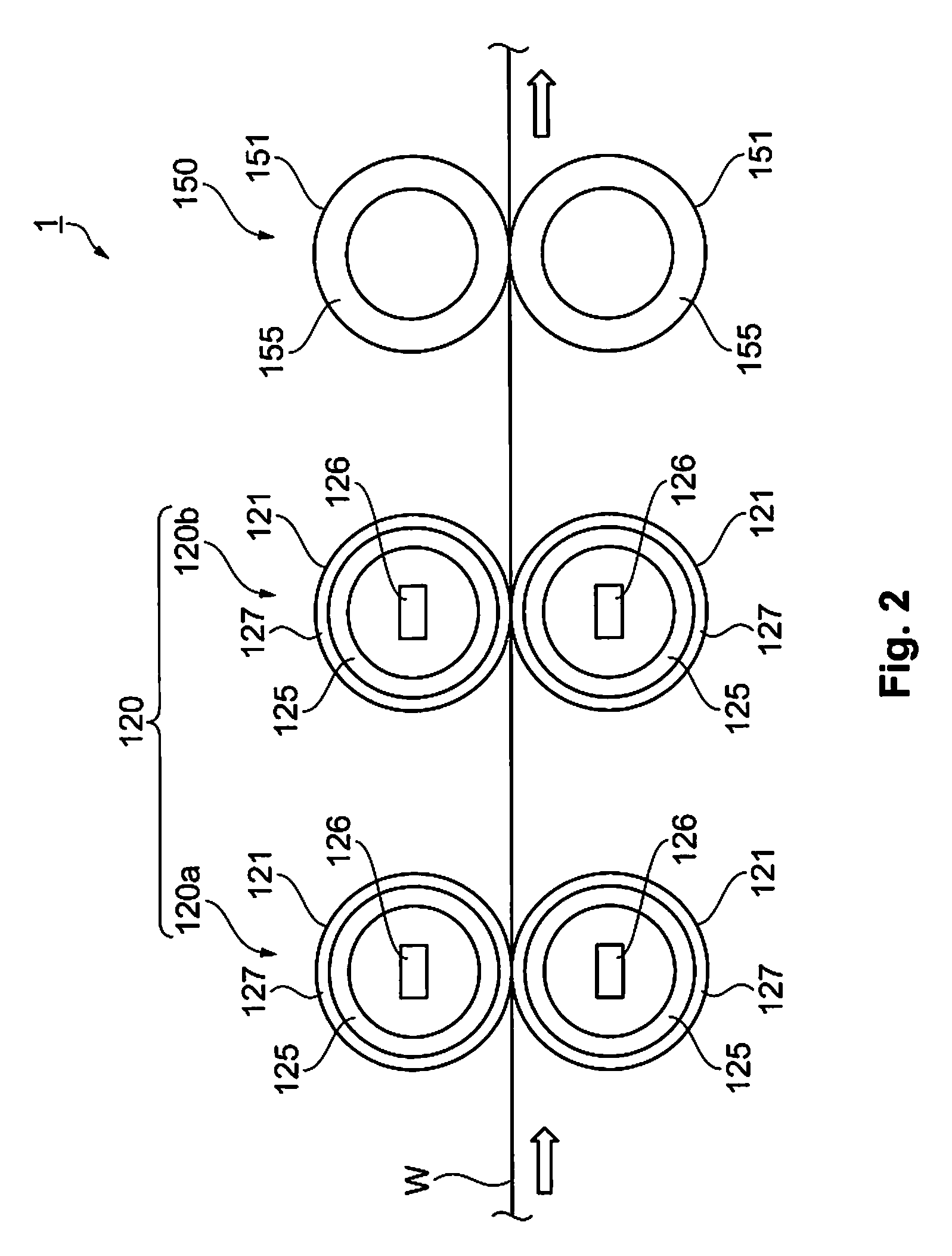
[0052]There is a configuration in the embodiment described above where the first and the second heating units 120a and 120b are arranged as the first pressurizing unit 120, but the configuration is not limited to this. For example, there may be a configuration where only the first heating roller 120a is arranged or there may be a configuration where three or more of the first pressurizing units 120 are arranged. In this case, the first pressurizing unit 120 is appropriately set according to the thickness, material properties, and the like of the web W (the sheet Pr) which is being manufactured. By doing this, it is possible to effectively manufacture (form) the sheet Pr (the web W).

modified example 3

[0053]There is a configuration in the embodiment described above where the first pressurizing unit 120 and the second pressurizing unit 150 have the format of pairs of rollers, but the configuration is not limited to this. For example, there may be a configuration with plate pressing device. Even with this, it is possible to obtain the same effects as described above.


PUM


Abstract

A sheet manufacturing apparatus includes a web forming unit configured to form a web which includes fibers and resin, and a first pressurizing unit and a second pressurizing unit configured to pressurize the web. The first pressurizing unit has a separation layer, is positioned on an upstream side of the second pressurizing unit in a transfer direction of the web, and is configured to heat the web. The second pressurizing unit is positioned on a downstream side of the first pressurizing unit in the transfer direction of the web, does not have a separation layer, and is configured not to heat the web. The pressurizing force from the first pressurizing unit is smaller than the pressurizing force from the second pressurizing unit.

Description

CROSS-REFERENCE TO RELATED APPLICATIONS[0001]This application claims priority to Japanese Patent Application No. 2013-207968 filed on Oct. 3, 2013. The entire disclosure of Japanese Patent Application No. 2013-207968 is hereby incorporated herein by reference.BACKGROUND[0002]1. Technical Field[0003]The present invention relates to a sheet manufacturing apparatus and a sheet manufacturing method.[0004]2. Related Art[0005]In the prior art, there is known a sheet manufacturing apparatus where a sheet is formed by a transfer medium, where additives and reinforcing materials are added to pulp fibers, being supplied on a mesh and passed through between heating rollers after a polymer emulsion is sprayed on as a binder (for example, refer to Japanese Examined Patent Application Publication No. S53-38785).[0006]Here, there is a problem in that the transfer medium becomes attached to a heating and pressurizing unit when the transfer medium is heated and pressurized. This is because resin suc...

Claims


Application Information

Patent Timeline
Patent Type & Authority Patents(United States)
IPC IPC(8): D21F3/08
CPCD21F3/08D21F3/0281D21F9/00
Inventor GOMI, KATSUHITO
Owner SEIKO EPSON CORP
Why Eureka
Try Eureka