Variable spray injector with nucleate boiling heat exchanger

a fuel injector and variable technology, applied in the direction of machines/engines, combustion types, lighting and heating apparatus, etc., can solve the problems of high hydrocarbon emissions of conventional spark ignition internal combustion engines, poor fuel ignition and combustibility, and excessive crank time, so as to maximize the resident time of fluid on the surface, enhance the turbulence, and enhance the fluid movement

Inactive Publication Date: 2015-07-07
VITESCO TECH USA LLC
View PDF19 Cites 6 Cited by
  • Summary
  • Abstract
  • Description
  • Claims
  • Application Information

AI Technical Summary

Benefits of technology

[0019]Numerous experimental investigations have sought to optimize heat transfer through convection in which turbulence, mixing, and fluid motion are enhanced, as well as conduction where surface area is maximized and resident time of the fluid on that surface is maximized. At the same time that convection and conduction are maximized, the generation of phase-change in the form of boiling was to be carefully avoided to prevent significant metered mass rate shift in flow due to gas fraction and the decrease in thermal conduction with film boiling creating insulating surfaces of vapor.
[0020]In accordance with embodiments of the invention, boiling is not avoided. Instead, boiling is enhanced, encouraged, and limited to nucleate boiling thereby advantageously expediting heat transfer. Additionally, nucleate boiling may be encouraged even below the vapor pressure of the fluid in what is called subcooled nucleate boiling. One or more embodiments of the invention deliberately create temperature gradients and nucleation sites for favorable generation of vapor bubbles such that generation and detachment of a relatively large quantity of relatively small vapor bubbles creates a phase change heat flux that is greater than that of the normal free-convection and conduction heat flux.

Problems solved by technology

During cold temperature engine start, the conventional spark ignition internal combustion engine is characterized by high hydrocarbon emissions and poor fuel ignition and combustibility.
Unless the engine is already at a high temperature after stop and hot-soak, the crank time may be excessive, or the engine may not start at all.
Such systems are expensive and redundant.
Once a useful heating method is available, the next challenge is transferring the heat from the appropriate loss component to the fuel to be heated.
These conventional methods suffer from a limit imposed by the thermal conductivity and surface area of the materials involved.
If one attempts to increase the heat flux into a given volume of fluid simply by increasing the temperature of the selectively heated components, the result is often exceeding the vapor pressure of the fuel for that new higher temperature and the generation of a wall film of vaporized fuel, the film boiling regime, that then reduces thermal conductivity because it is less efficient to transfer heat into a gas than to transfer heat into a liquid.

Method used


Image

  • Variable spray injector with nucleate boiling heat exchanger
  • Variable spray injector with nucleate boiling heat exchanger
  • Variable spray injector with nucleate boiling heat exchanger

Examples


Embodiment Construction

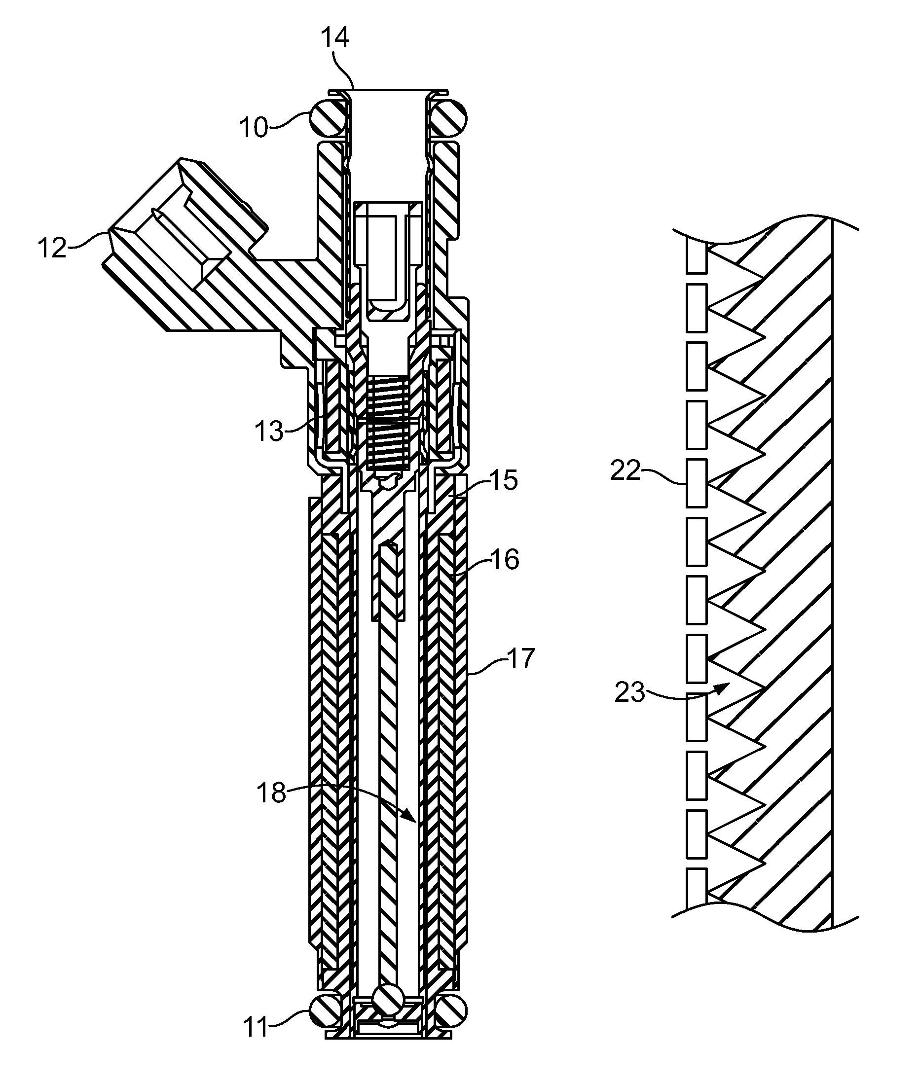
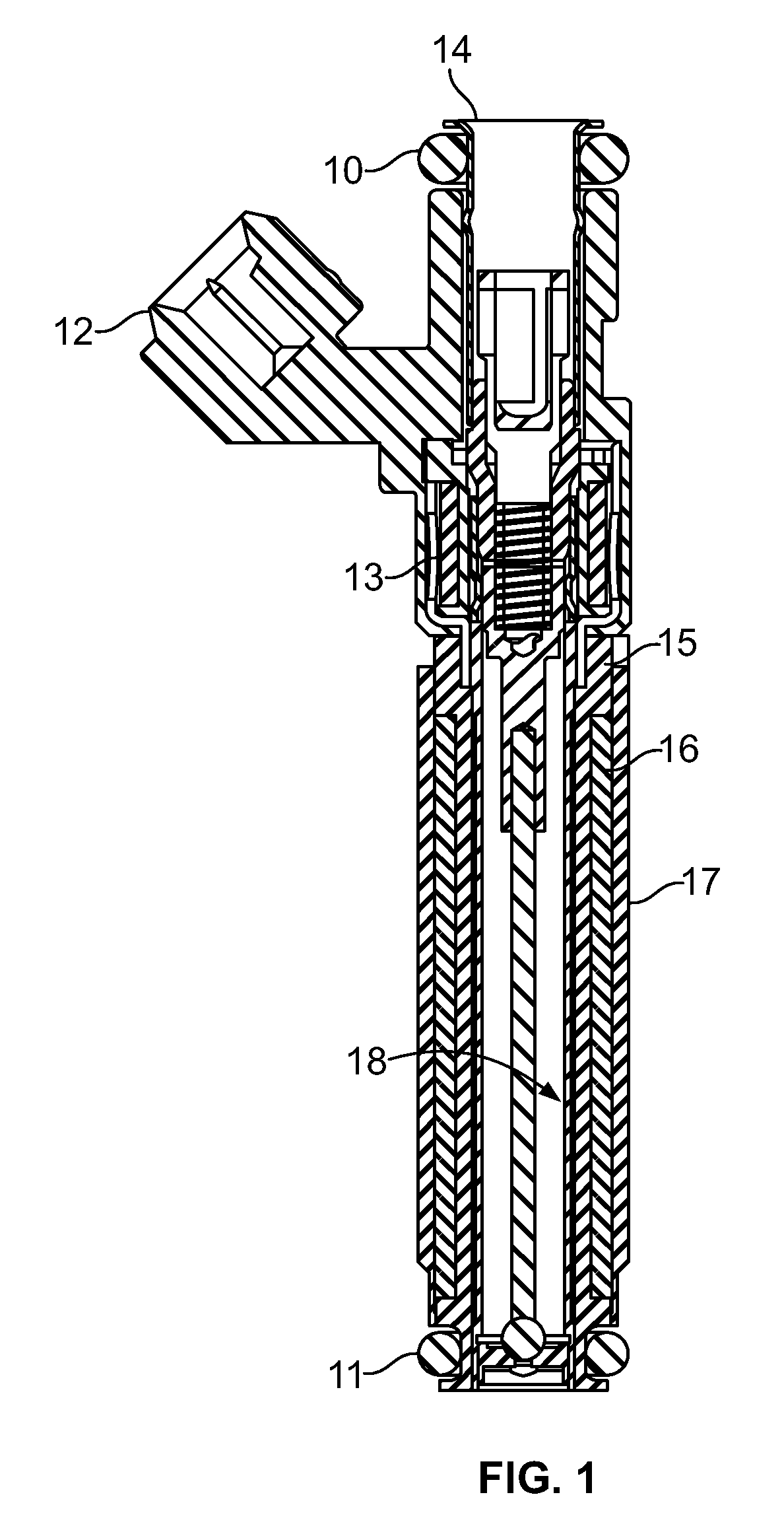
[0026]Embodiments of the invention are described herein as implemented in a variable spray fuel injector with an induction heated loss component. Referring to FIG. 1, which is an inductively heated variable spray fuel injector, the basic configuration includes a sealing method to the source of fuel supply, O-ring 10, between the supply and the fuel inlet tube 14 structure. The electrical connector 12 provides a means of conducting power to solenoid valve coil 13 and inductive heater coil 16. The appropriate loss component, whose surface 18 will provide the control surface for nucleated boiling heat transfer, is surrounded by bobbin 15 but is separated by a thermal barrier or insulator from the loss component. A heater coil 16 is placed upon the bobbin and is confined between the bobbin and a housing or shell 17. The intake manifold of the internal combustion engine is sealed to the injector with a sealing method, such as an O-ring 11.

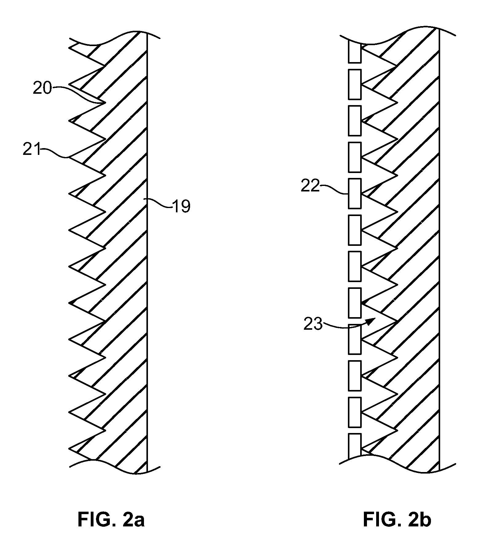
[0027]With reference to FIG. 2a, an appropriate l...


PUM


Abstract

A heat exchanger, internal to an injector for a variable spray fuel injection system, uses nucleate boiling to maximize the heat flux from the heated metal to the fuel, wherein the nucleate boiling occurs along a control surface characterized by features conducive to generating detaching bubbles to transfer heat energy in a vapor flux. The source of heat flux may be an induction heater coil magnetically coupled to an appropriate loss component so that fuel inside a fuel component is heated to a desired temperature.

Description

CROSS-REFERENCE TO RELATED APPLICATIONS[0001]This application is a non-provisional of, and claims priority to the Apr. 22, 2011, filing date of, U.S. provisional patent application Ser. No. 61 / 478,404, entitled Variable Spray Injector with Nucleate Boiling Heat Exchanger, the entire content of which is incorporated herein by reference.[0002]And this application is related to the following U.S. non-provisional patent applications filed on the same day as this application:[0003]Synchronous Full-Bridge Power Oscillator with Leg Inductors, invented by Perry Czimmek, and identified by Ser. No. 13 / 332,501;[0004]Synchronous Full-Bridge Power Oscillator, invented by Perry Czimmek, and identified by Ser. No. 13 / 332,506;[0005]Synchronized Array Bridge Power Oscillator, invented by Perry Czimmek and Mike Hornby, and identified by Ser. No. 13 / 332,517;[0006]Synchronized Array Power Oscillator with Leg Inductors, invented by Perry Czimmek and Mike Hornby, and identified by Ser. No. 13 / 332,521; an...

Claims


Application Information

Patent Timeline
Patent Type & Authority Patents(United States)
IPC IPC(8): F02M53/06F02M51/06
CPCF02M53/06
Inventor CZIMMEK, PERRYSAYAR, HAMID
Owner VITESCO TECH USA LLC
Why Eureka
Try Eureka