Gradational insertion of an artificial lift system into a live wellbore

a technology of artificial lift system and wellbore, which is applied in the direction of borehole/well accessories, drilling casings, drilling pipes, etc., can solve the problems of limited deployment of cable inserted in coil tubing, cost, reliability and availability of coiled tubing units, and the inability to use a broader range of cables

Active Publication Date: 2015-07-14
SCHLUMBERGER TECH BV
View PDF11 Cites 21 Cited by
  • Summary
  • Abstract
  • Description
  • Claims
  • Application Information

AI Technical Summary

Benefits of technology

[0006]In another embodiment, a pressure control assembly for inserting a downhole assembly into a live wellbore, includes: a first clamp comprising a housing having a bore therethrough and bands or slips, each band or slip radially movable relative to the first clamp housing into and from the first clamp bore; a second clamp comprising a housing having a bore therethrough and bands or slips, each second band or slip radially movable relative to the second clamp housing into and from the second clamp bore; a preventer or packer comprising a housing having a bore therethrough, a seal, and an actuator operable to extend and retract the seal into and from the preventer or packer housing bore; an isolation valve comprising a housing having a bore therethrough and a valve member operable to open and close the valve bore; and a driver comprising a housing having a bore therethrough and a wrench radially movable relative to the housing into and from the driver bore, the wrench comprising a motor and a socket, the socket operable to engage a threaded fastener and the motor operable to rotate the socket, wherein the clamp housings, the preventer or packer housing, the valve housing, and the driver housing are connected to form a continuous bore through the assembly.

Problems solved by technology

There has been limited deployment of cable inserted in coil tubing where the coiled tubing is utilized to support the weight of the equipment and cable.
Although this system is seen as an improvement over jointed tubing, the cost, reliability and availability of coiled tubing units have prohibited use on a broader basis.

Method used


Image

  • Gradational insertion of an artificial lift system into a live wellbore
  • Gradational insertion of an artificial lift system into a live wellbore
  • Gradational insertion of an artificial lift system into a live wellbore

Examples


Embodiment Construction

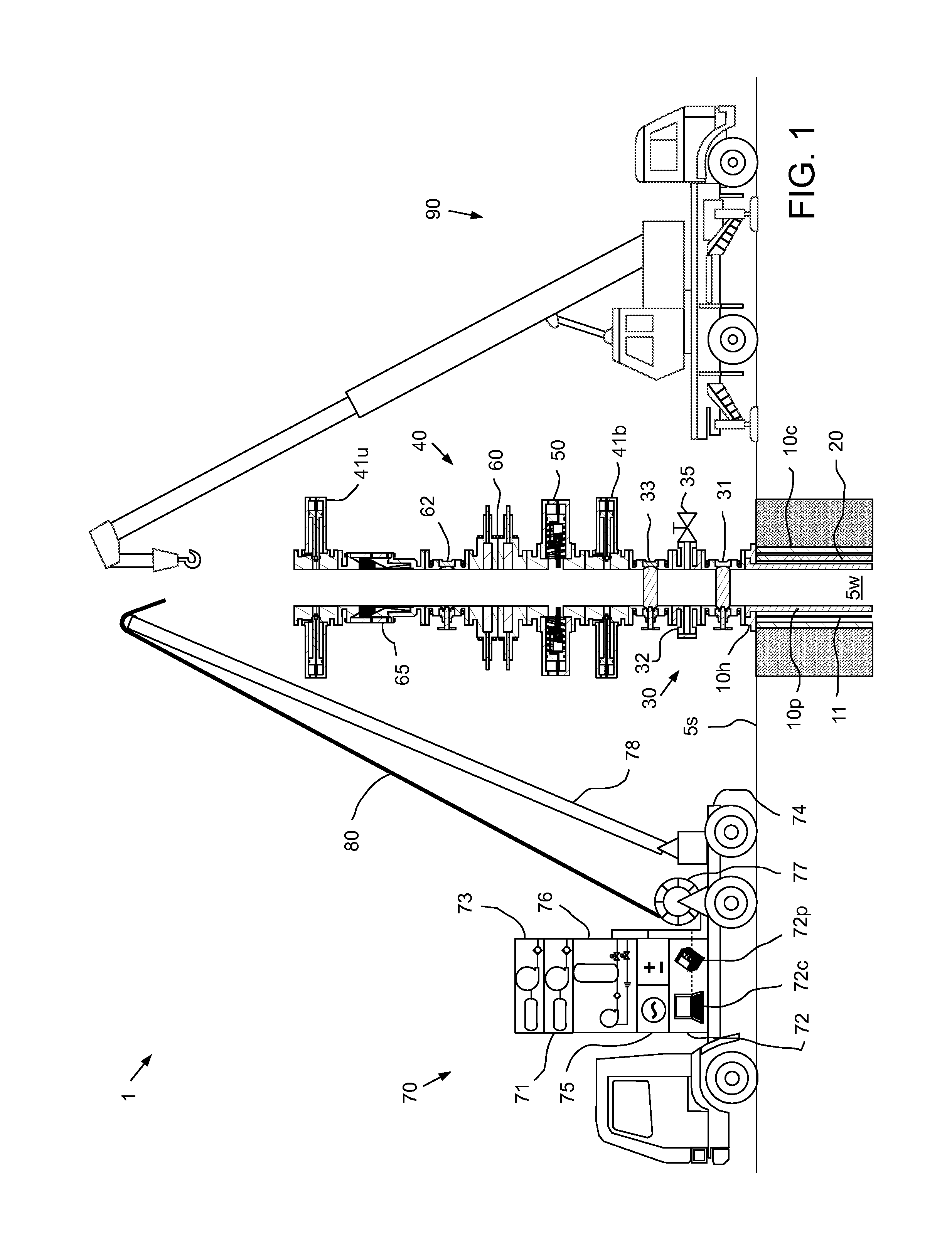
[0016]FIG. 1 illustrates deployment of a launch and recovery system (LARS) 1 to a wellsite, according to one embodiment of the present invention. The LARS 1 may include a pressure control assembly 40, a wireline truck 70, a crane 90, a lubricator 200 (FIG. 6A), and one or more running tools 250a,b (FIGS. 6B and 7A).

[0017]A wellbore 5w has been drilled from a surface 5s of the earth into a hydrocarbon-bearing (i.e., crude oil and / or natural gas) reservoir 6 (FIG. 14A). A string of casing 10c has been run into the wellbore 5w and set therein with cement (not shown). The casing 10c has been perforated 9 (FIG. 14B) to provide to provide fluid communication between the reservoir 6 and a bore of the casing 10c. A wellhead 10h has been mounted on an end of the casing string 10c. A string of production tubing 10p extends from the wellhead 10h to the reservoir 6 to transport production fluid 7 (FIG. 14C) from the reservoir 6 to the surface 5s. A packing 8 (FIG. 14A) has been set between the ...


PUM


Abstract

A method of inserting a downhole assembly into a live wellbore, includes: assembling a pressure control assembly (PCA) onto a production tree of the live wellbore; inserting a first deployment section of the downhole assembly into a lubricator; landing the lubricator onto the PCA; connecting the lubricator to the PCA; lowering the first deployment section into the PCA; engaging a clamp of the PCA with the first deployment section; after engaging the clamp, isolating an upper portion of the PCA from a lower portion of the PCA; and after isolating the PCA, removing the lubricator from the PCA.

Description

BACKGROUND OF THE INVENTION[0001]1. Field of the Invention[0002]Embodiments of the present invention generally relate to gradational insertion of an artificial lift system into a live wellbore.[0003]2. Description of the Related Art[0004]The oil industry has utilized electric submersible pumps (ESPs) to produce high flow-rate wells for decades, the materials and design of these pumps has increased the ability of the system to survive for longer periods of time without intervention. These systems are typically deployed on the tubing string with the power cable fastened to the tubing by mechanical devices such as metal bands or metal cable protectors. Well intervention to replace the equipment requires the operator to pull the tubing string and power cable requiring a well servicing rig and special spooler to spool the cable safely. The industry has tried to find viable alternatives to this deployment method especially in offshore and remote locations where the cost increases signific...

Claims


Application Information

Patent Timeline
Patent Type & Authority Patents(United States)
IPC IPC(8): E21B19/16E21B43/12E21B33/072
CPCE21B33/072E21B19/16E21B19/161E21B43/128
Inventor WETZEL, JAMES RUDOLPHSHELINE, EVANGRIFFITHS, NEIL
Owner SCHLUMBERGER TECH BV
Why Eureka
Try Eureka