
Tensioner

a technology of tensioner and ring, which is applied in the direction of belt/chain/ring, mechanical equipment, belt/chain/ring, etc., can solve the problems of carbon steel use, rustproofing and heat treatment, and the need for abrasion to be imparted

Inactive Publication Date: 2015-07-14
TSUBAKIMOTO CHAIN CO
View PDF11 Cites 0 Cited by
  • Summary
  • Abstract
  • Description
  • Claims
  • Application Information

AI Technical Summary

Benefits of technology

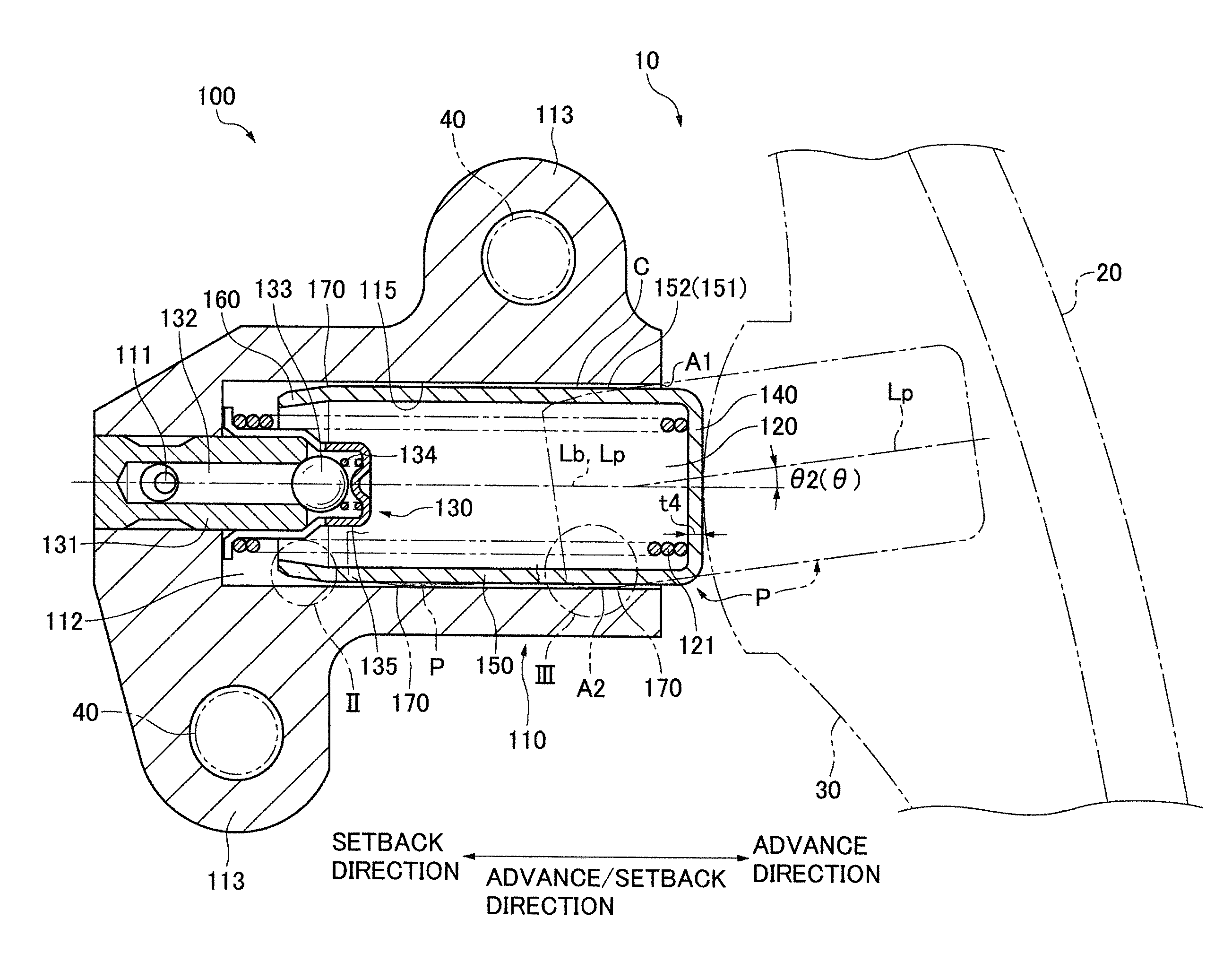
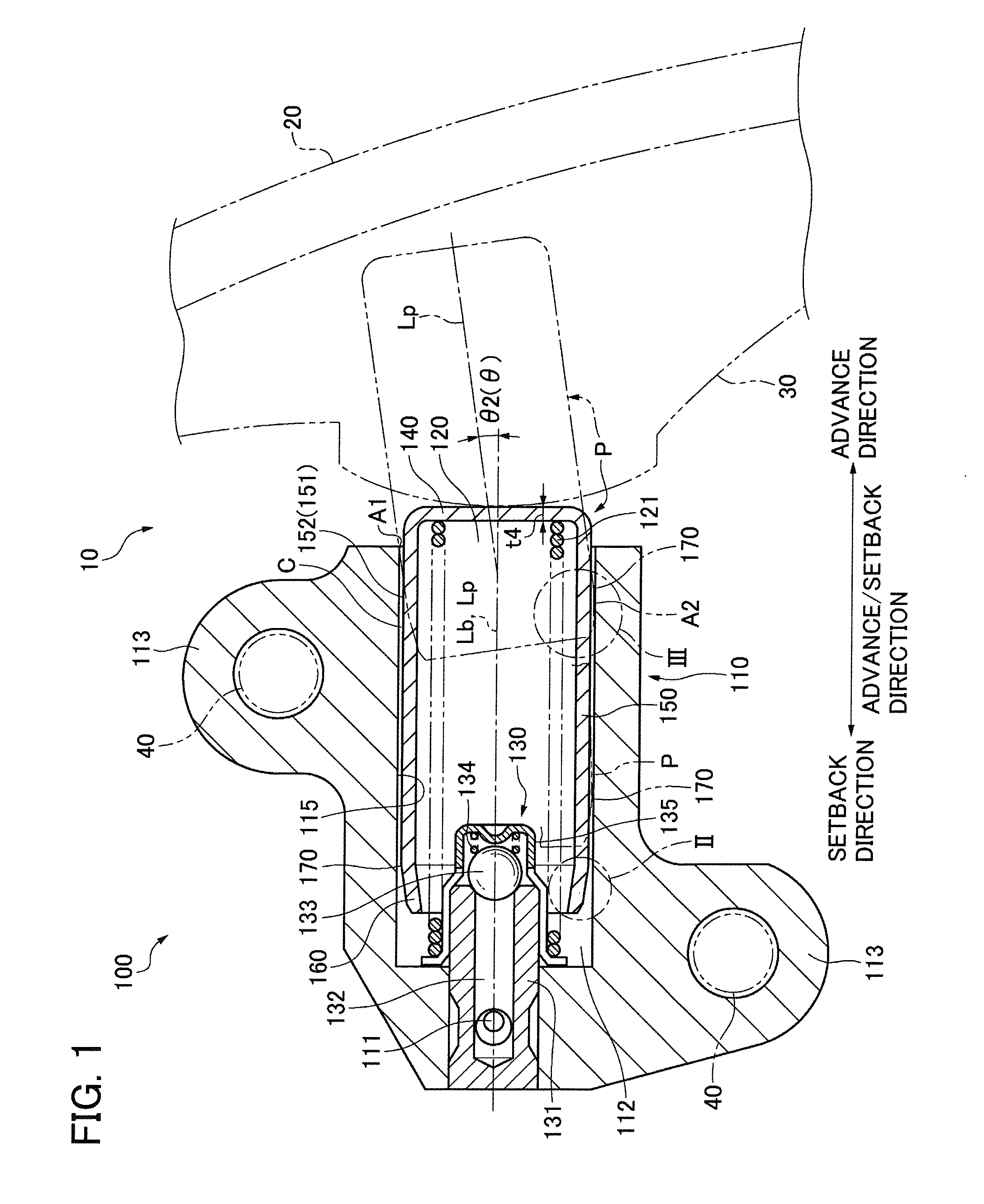
[0016]Advantages of the first aspect of the invention include a reduction in the weight of the plunger because its wall can be made thin, avoidance of deformation of the plunger, improved sliding of the plunger, improved responsiveness of the tensioner to fluctuating tension, a cost reduction resulting from the elimination of the need for forging or cutting, and elimination of the need for treatments such as heat treatment to impart wear resistance and durability to the plunger. In addition, equalization of the angle of the taper at the boundary where the end wall meets the cylindrical outer wall with the maximum inclination of the plunger, reduces wear in the vicinity of the boundary and improves the durability of the plunger and the tensioner housing.
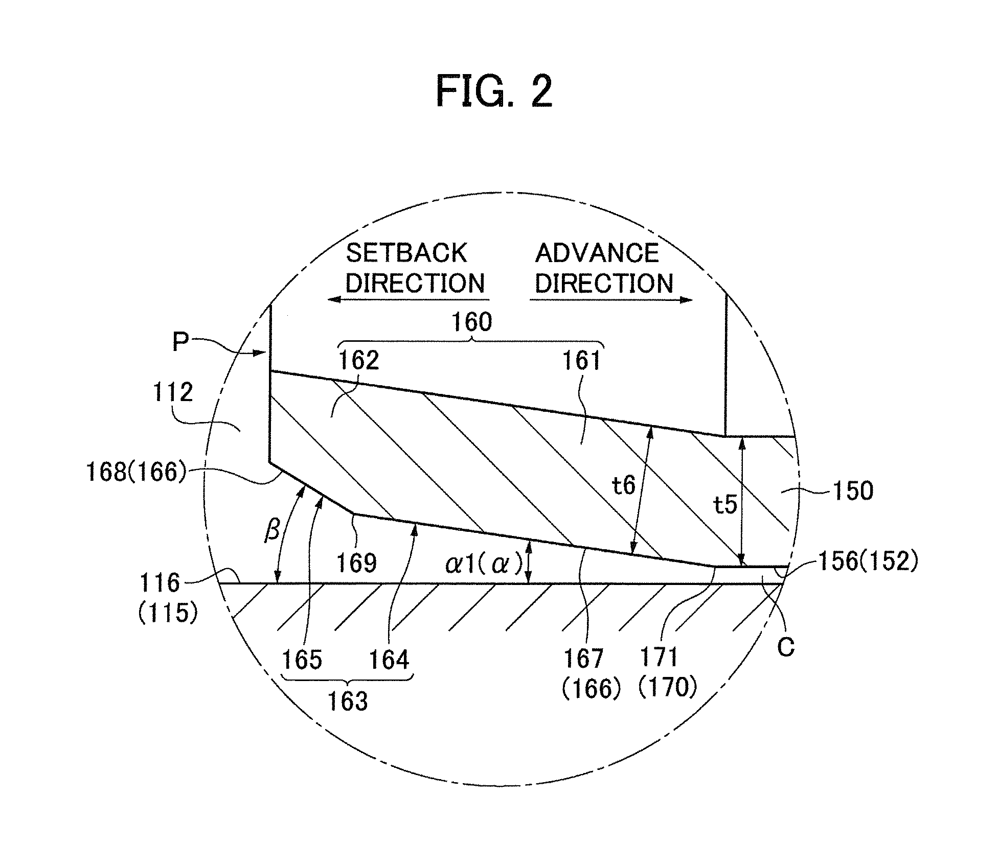
[0030]Because the radius of the outer circumferential surface of the rear end wall varies continuously and smoothly without a bend, insertion of the plunge into the plunger-accommodating hole can be carried out more smoothly in the assembly of the tensioner.

Problems solved by technology

However, the use of carbon steel has a drawback in that treatments such as heat treatment and rustproofing are required to impart abrasion resistance to the material after forming the plunger by forging or cutting.

Method used


Image

  • Tensioner
  • Tensioner
  • Tensioner

Examples


second embodiment

[0075]In a second embodiment, shown in FIG. 4, outer circumferential surface 264 is a surface of revolution in which intersection line 267 is a convex arc-shaped curve. The outer circumferential surface 265 is a surface of revolution in which the intersection line 268 is also a convex arc-shaped curve having a radius of curvature smaller than the radius of curvature of intersection line 267.

[0076]The outer circumferential surface 263 is therefore a two-part surface composed of surfaces 264 and 265 which are continuous with each other and meet at a connecting location 269 formed by the outer circumferential surfaces 264 and 265. Intersection lines 267 and 268, therefore compose a rear end intersection line 266. The radius of curvature of the intersection line 267 is greater than the thickness t6 of the plunger wall. As the radius of curvature becomes larger, the contact pressure in the vicinity of the boundary 170 is reduced.

[0077]In FIG. 4, angle α is an angle formed by a tangent li...

third embodiment

[0086]In a third embodiment, shown in FIG. 5, the outer circumferential surface 363 of the rear end wall 160 of a plunger P is a surface of revolution in which a rear end intersection line 366 is an arc-shaped convex curve the radius of curvature of which decreases continuously proceeding in the setback direction from the location 171 where the curve meets the sliding contact surface 152.

[0087]The maximum radius of the intersection line 366 is greater than the thickness t6 of the plunger wall, in order to reduce the contact pressure in the vicinity of the boundary 170.

[0088]The angle γ is formed by a tangent line Lt and intersection line 116 on the inner wall of the plunger-accommodating hole. The tangent line is inclined so that, proceeding in the setback direction, the tangent line becomes farther away from intersection line 116. A specific angle γ1 is the value of angle γ for a tangent at the point 171 at which intersection line 366 meets sliding contact intersection line 156. An...


PUM


Abstract

In a tensioner having a housing and a plunger protruding in an advancing direction from a plunger-accommodating hole formed in the housing. The plunger has a cylindrical outer wall for sliding contact with the wall of the plunger-accommodating hole, and a tapered the rear end wall. A small clearance between the cylindrical outer wall of the plunger and the wall of the plunger-accommodating hole allows the plunger to become inclined by a small amount, which increases as the plunger advances. The angle of the taper at a boundary where the end wall meets the cylindrical outer wall is substantially equal to the maximum inclination of the plunger when the plunger is in its fully advanced condition.

Description

CROSS REFERENCE TO RELATED APPLICATION[0001]The disclosure of Japanese Patent Application No. 2012-130119, filed on Jun. 7, 2012, and on which this application claims priority, is incorporated by reference.FIELD OF THE INVENTION[0002]This invention relates to a tensioner for applying tension to an endless, flexible, transmission medium, e.g., a transmission chain, and more specifically to a plunger that is slidable in a tensioner housing and that moves in an advancing direction or in a setback direction in accordance to fluctuating tension in the transmission medium.[0003]The tensioner can be a hydraulic tensioner, for example, and the transmission medium can be a timing chain for transmitting rotation from a crankshaft to one or more valve-operating camshafts in an internal combustion engine.BACKGROUND OF THE INVENTION[0004]A conventional tensioner includes a housing with a plunger-accommodating hole, a plunger protruding from the plunger-accommodating hole and slidable therein in ...

Claims


Application Information

Patent Timeline
Patent Type & Authority Patents(United States)
IPC IPC(8): F16H7/08
CPCF16H7/08F16H7/0836F16H7/0848F16H2007/0806F16H2007/0812F16H2007/0859
Inventor KUREMATSU, YUJIYOSHIDA, OSAMU
Owner TSUBAKIMOTO CHAIN CO
Learn More