Laminated diffractive optical element

a diffractive optical element and diffractive optical technology, applied in the field of laminated diffractive optical elements and optical systems, can solve the problems of difficulty in sufficiently correcting chromatic aberration, and achieve the effect of reducing shading and reducing transmittance variation

Inactive Publication Date: 2015-07-21
CANON KK
View PDF16 Cites 25 Cited by
  • Summary
  • Abstract
  • Description
  • Claims
  • Application Information

AI Technical Summary

Benefits of technology

[0021]In view of the background art, the present invention provides a laminated diffractive optical element having reduced variation in transmittance and an optical system using the same by reducing shading on the image surface resulting from the difference in transmittance of the optical element.

Problems solved by technology

However, it has been difficult to correct chromatic aberration sufficiently in the case where the configuration or number of lenses is limited or in the case where glass materials for use are limited.
On this occasion, diffracted light beams having orders other than the design order form images at sites different from the site where the light beam having the design order forms the image, causing flare.

Method used


Image

  • Laminated diffractive optical element
  • Laminated diffractive optical element
  • Laminated diffractive optical element

Examples


example 1

[0067]A material (a) for forming a first layer having high refractive index and low dispersion characteristics and a material (b) for forming a second layer having low refractive index and high dispersion characteristics were manufactured as follows.

[0068][A Method for Manufacturing the Material (a) for Forming a Layer having High Refractive Index and Low Dispersion Characteristics]

[0069]ZrO2 fine particles having an average primary particle diameter of 3 nm were dispersed using a surface-treating agent and toluene solvent to prepare slurry of 10 wt % ZrO2 fine particles. A photocurable acrylic resin was prepared as a resin. Sumipast Black HB and SDO-13 manufactured by Sumika Chemtex Co., Ltd. were prepared as colorants.

[0070]The slurry was compounded into 22.6 vol % ZrO2 fine particles relative to the resin volume, blended, and compatibly dissolved. Subsequently, the colorants were compounded into 0.21 wt % Sumipast Black HB and 0.26 wt % SDO-13 relative to the total weight of the ...

examples 2 to 5

[0102]In Examples 2 to 5, in manufacturing of the material (a), slurry was compounded into one of 5.4, 0.0, 20.0, and 10.1 vol % ZrO2 fine particles relative to the resin volume in comparison to Example 1. Each of the materials (a) 202 to 205 was produced as in Example 1 except that one of 0.19, 0.12, 0.15, and 0.08 wt % Sumipast Black HB was compounded relative to the total weight of the resin and the ZrO2 fine particles and one of 0.24, 0.15, 0.18, and 0.10 wt % SDO-13 was compounded relative to the total weight of the resin and the ZrO2 fine particles.

[0103]In Examples 2 to 5, in manufacturing of the material (b), each of the materials (b) 302 to 305 was produced as in Example 1 except for the alteration to one of 15.0 and 7.5 vol % ITO fine particles relative to the resin volume in comparison to Example 1 and the alteration from a photocurable fluorine-containing acrylic resin to a photocurable acrylic resin in Examples 4 and 5.

[0104]In Examples 2 to 5, in manufacturing of the l...


PUM


Abstract

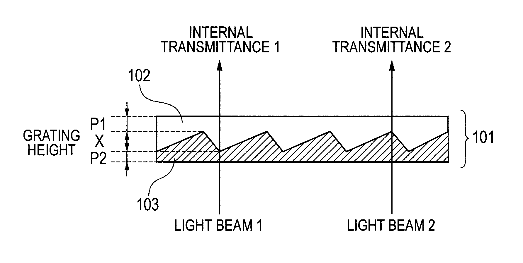
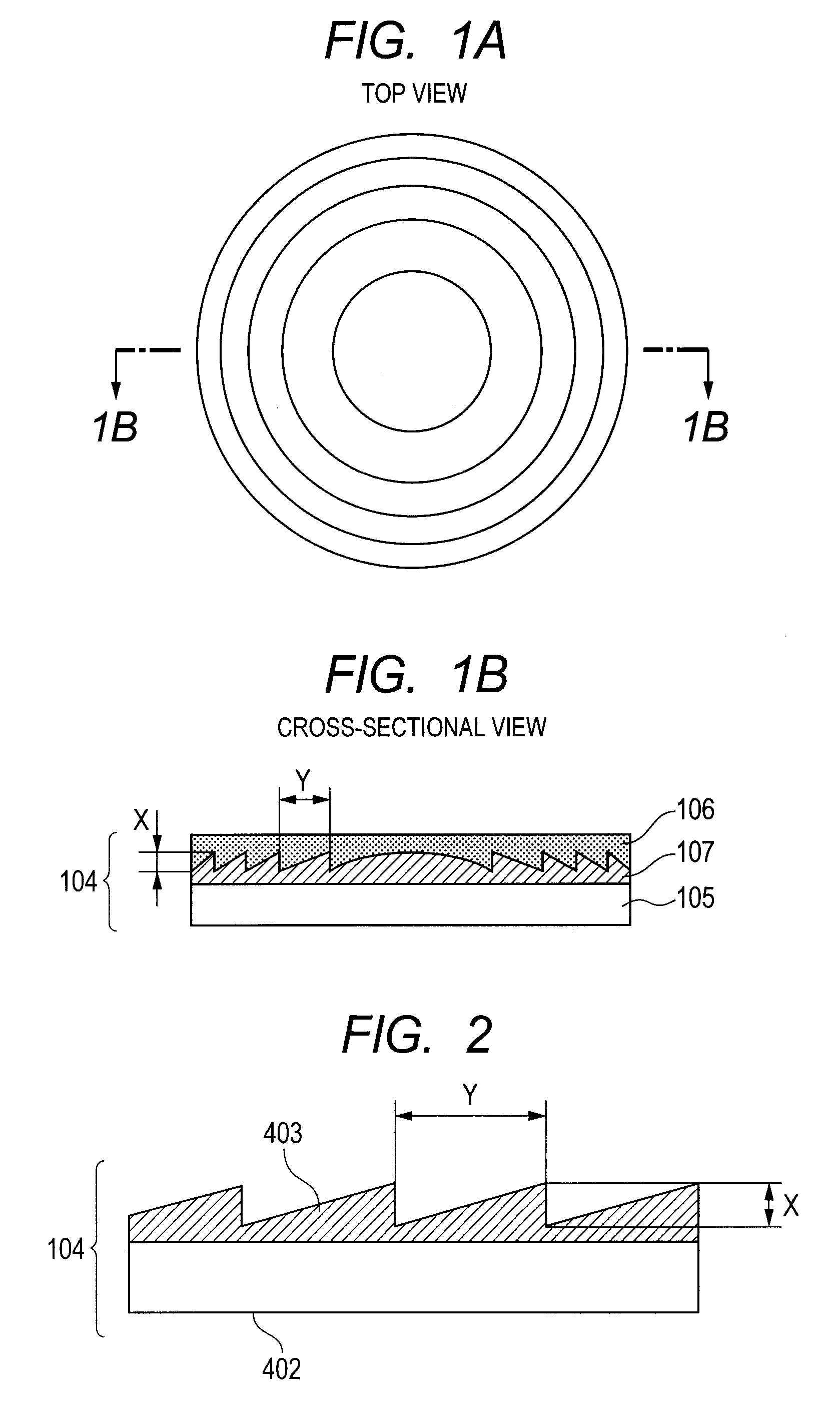
A laminated diffractive optical element including a colorant-containing first layer having a diffraction grating surface with a grating height X and a second layer closely stacked on the diffraction grating surface of the first layer, wherein the relation of internal transmittances Tλ, a and Tλ, b of a material (a) for forming the first layer and a material (b) for forming the second layer satisfies the following (Formula 1) and the relation of the maximum and minimum internal transmittances Tλ, MAX and Tλ, MIN of the laminated diffractive optical element satisfies the following Formula (2):2.0%≦|Tλ, a−Tλ, b|  (Formula 1)Tλ, MAX−Tλ, MIN≦8.0%   (Formula 2)This reduces shading on the image surface resulting from the difference in transmittance of the optical element to provide a laminated diffractive optical element having reduced variation in transmittance.

Description

TECHNICAL FIELD[0001]The present invention relates to a laminated diffractive optical element and an optical system, and more particularly to a laminated diffractive optical element used for an imaging optical system such as a camera.BACKGROUND ART[0002]In a conventional refracting optical system using refraction of light, chromatic aberration is reduced by a combination of lenses made of glass materials having different dispersion characteristics. For example, an object lens of a telescope employs a combination of a positive lens made of low-dispersion glass and a negative lens of high-dispersion glass to correct chromatic aberration arising on the axis. However, it has been difficult to correct chromatic aberration sufficiently in the case where the configuration or number of lenses is limited or in the case where glass materials for use are limited.[0003]Accordingly, it is known that chromatic aberration can be inhibited with a small number of lenses when a refractive optical ele...

Claims


Application Information

Patent Timeline
Patent Type & Authority Patents(United States)
IPC IPC(8): G02B5/18G02B27/00
CPCG02B5/1866G02B5/1852G02B5/1876G02B27/0037G02B5/18
Inventor IWASA, HIDEFUMIUKUDA, HIDEO
Owner CANON KK
Why Eureka
Try Eureka