Packet tracing through control and data plane operations

a control plane and packet tracing technology, applied in the field of network, can solve problems such as packet loss, cumbersome and impractical debugging, and customer escalation of problems to vendors,

Inactive Publication Date: 2015-07-21
AVAGO TECH INT SALES PTE LTD
View PDF33 Cites 17 Cited by
  • Summary
  • Abstract
  • Description
  • Claims
  • Application Information

AI Technical Summary

Benefits of technology

[0012]Second, the switch develops a response tracepath packet which includes the identity of the switch where the response packet is being sent from as well as the payload of the forward tracepath packet. This response tracepath packet is sent out the port where the forward tracepath packet was received, so that the response tracepath packet will go to the source of the forward tracepath packet. If a loop was detected, this error information is also placed in the payload. When a response tracepath packet is received at a switch, the switch parses the payload looking for the switch's own information placed in the forward tracepath packet to determine which port received the forward tracepath packet, which information is preferably included in the appended information in addition to the switch identity, so that the return response tracepath packet can be sent out that port. If the switch's identity is not present in the payload, the response tracepath packet is a data plane response tracepath packet and a table developed during the forward tracepath packet operations is consulted to determine the egress port. This process is repeated at each switch or until the original source is reached by the response tracepath packet. This use of the same port results in the response tracepath packet traveling the same route as the forward tracepath packet, which insures that it will reach the original source, thus avoiding potential forwarding errors. By using the payload from the forward tracepath packet at each hop, the original source will receive response tracepath packets from each hop until an error occurs, if any, with the path up to the point of loss provided in the last response tracepath packet received.
[0015]When broadcast or multicast packets need to be analyzed, the above operations could result in a flood of response tracepath packets to the original source. To simplify operation under those conditions, only selected switches in the network will have the capability enabled, as opposed to the prior example where it was assumed that the capability was enabled in all switches. This reduces the number of response tracepath packets to a more manageable number. To get the entire flooding tree, different switches can be enabled and the same packet addressing used until all switches have been used. The results can then be merged to reveal the overall paths.
[0016]As can be seen, the above operations verify both the control and data planes, rather than just the control plane in the prior art. Blackholes are readily detected based on determining and evaluating the last response tracepath packet in either plane. Layer 2 loops are readily detected. BUM (broadcast, unicast, multicast) packets can be used to allow full BUM tree analysis. The operations can be done without reconfiguring the network or stopping normal production operations, other than the operation being debugged. This allows debugging to be done during normal hours and as desired, not on a scheduled basis. In addition, the nature of the response tracepath packets allows the customer, rather than the vendor, to perform the majority of the debugging. The operations also work through the newer topologies such as fabrics, vLAGs and MCTs.

Problems solved by technology

However, this debugging is cumbersome and impractical today.
This causes the customer to escalate the problems to the vendors.
Studies have shown that very high percentages of these escalations involve packet loss and in each case the great majority of the time is spent identifying the culprit network node.
Even for the vendors there is a lack of industry tools to easily debug layer-2 networks along the forwarding path as often multiple tools are needed to trace a single end-end layer-2 path.
Indeed, there is no mechanism to locate layer-2 loops.
The debugging is made more complicated because many problems have the same symptoms.
Further, as the problems are present on production networks, no configuration changes can be done, there is live production background traffic and there is limited time to do the debugging.

Method used


Image

  • Packet tracing through control and data plane operations
  • Packet tracing through control and data plane operations
  • Packet tracing through control and data plane operations

Examples


Embodiment Construction

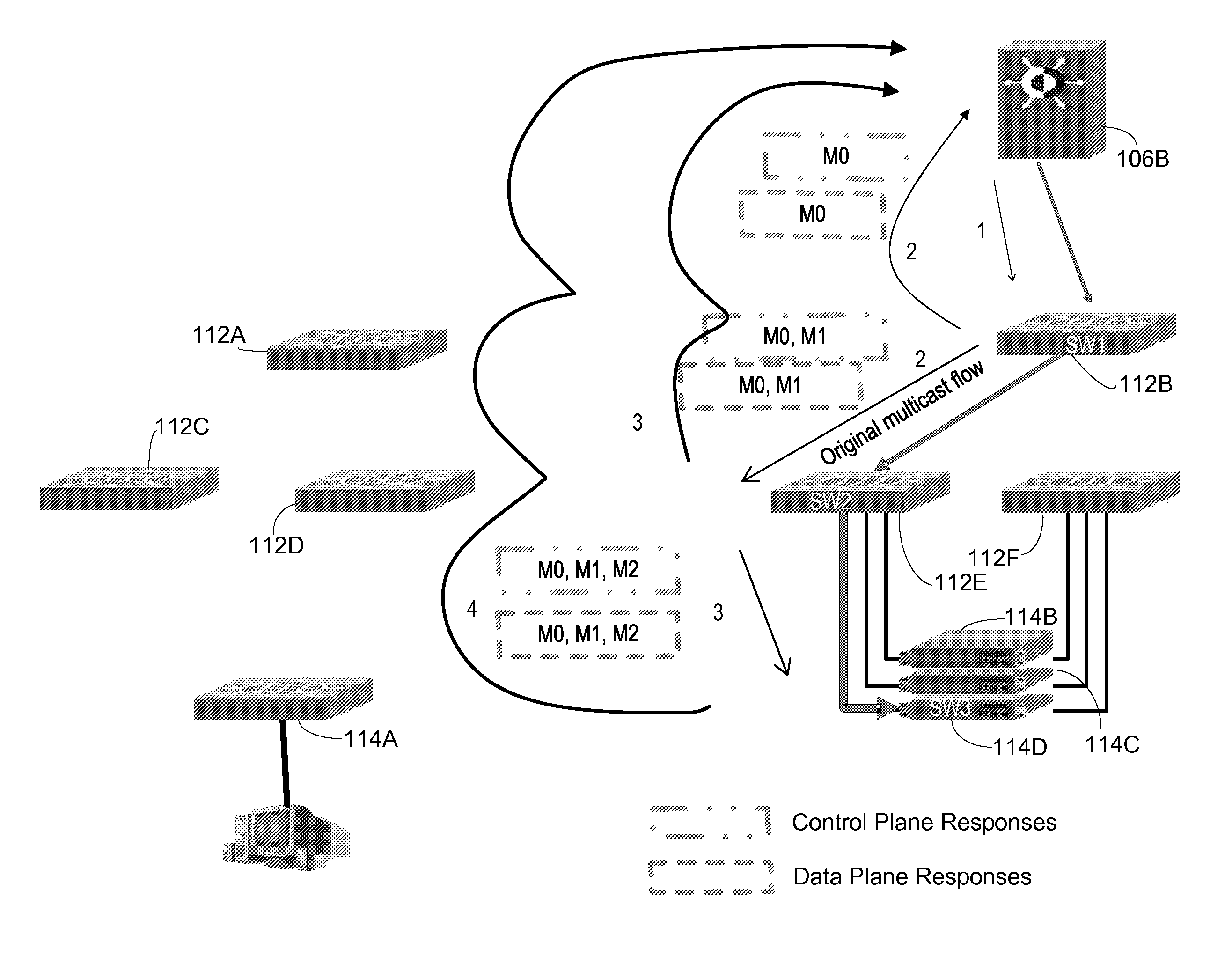
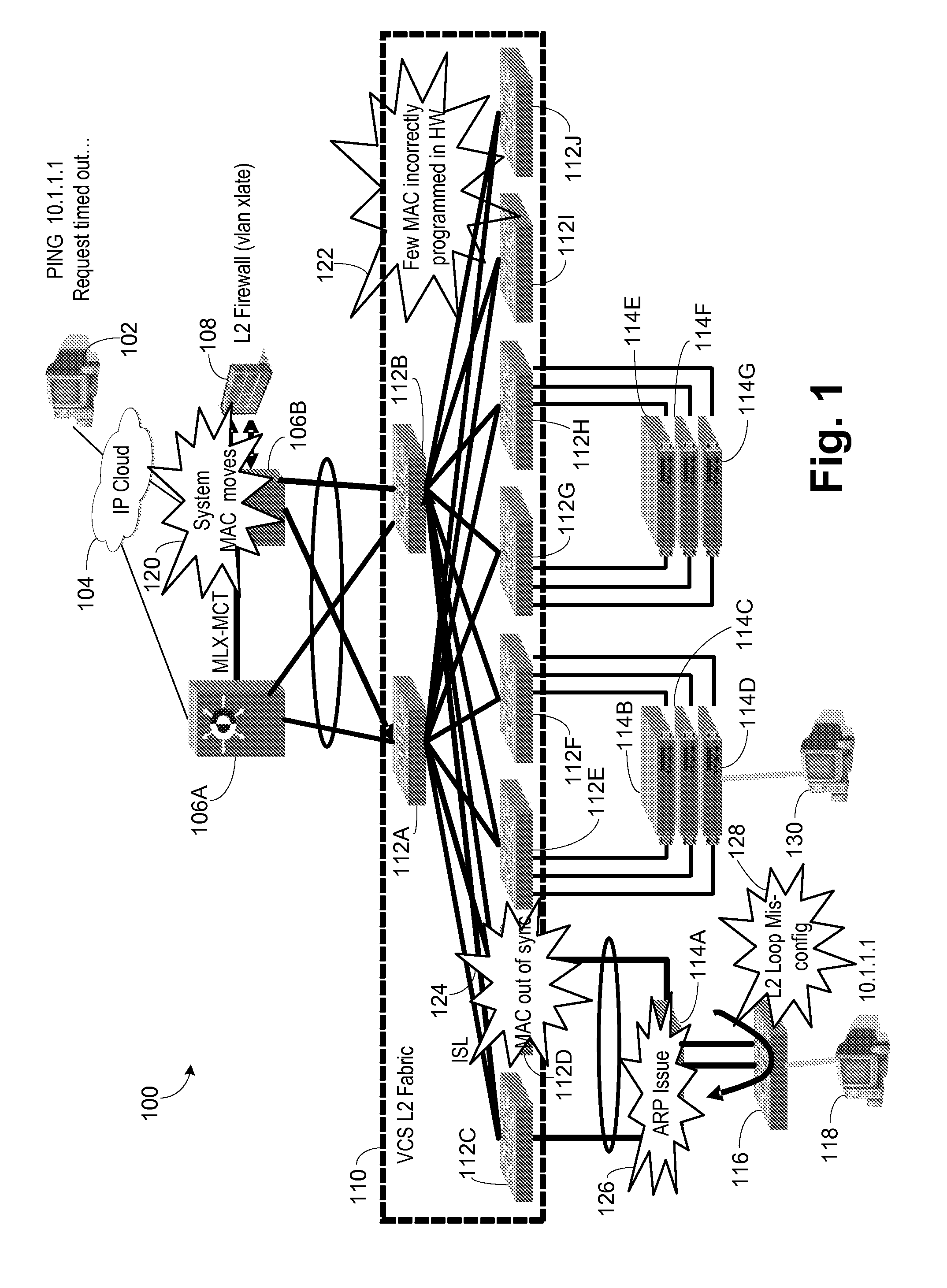
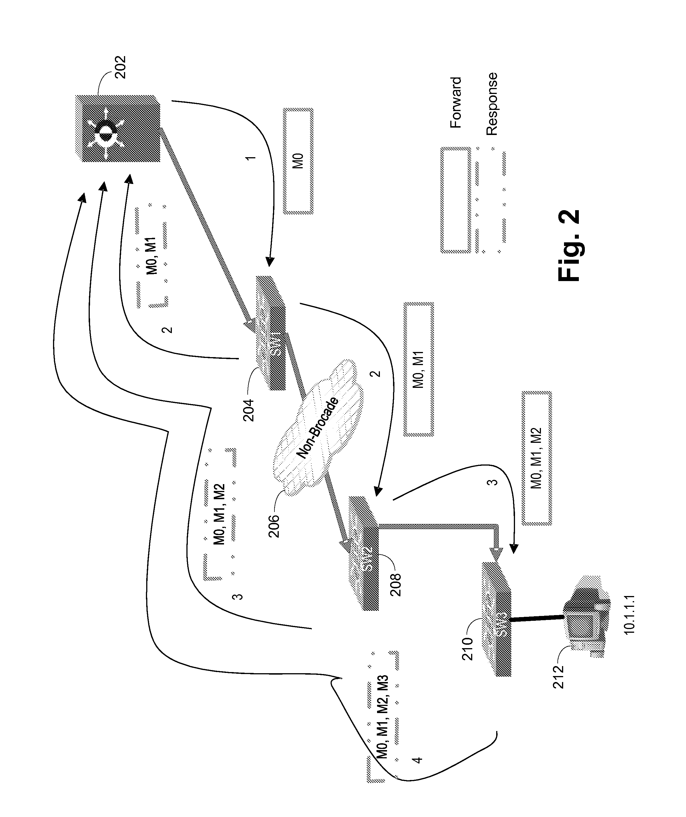
[0029]Referring now to FIG. 1, an exemplary network 100 is shown. An external workstation 102 is connected to an IP cloud 104, such as the Internet, which in turn is connected to routers 106A, 106B. The routers could be MLX routers from Brocade Communications Systems, Inc. (Brocade). A Layer 2 firewall 108 performs VLAN translations and other firewall functions and is connected to the routers 106A, 106B. The routers 106A, 106B are connected to a Layer 2 fabric no, such as the VCS fabric from Brocade. The Layer 2 fabric no is formed by a series of switches 112A-J, example switches being VDX switches from Brocade. A series of stackable edge switches 114A-G are illustrated as being connected to the Layer 2 fabric no. Example stackable edge switches are FCX switches from Brocade. Another switch 116 is connected to switch 114A in the example to provide a switch connected to a local workstation 118.

[0030]In the illustrated embodiment external workstation 102 pings the local workstation 11...


PUM


Abstract

Improved debugging capabilities for network packet path tracing. Embodiments trace both the control and data planes. During control plane operations each switch appends its identity to the payload, providing a full trace of the control plan path. Responses containing the forward path payload are provided back at each hop, the responses being routing back by tracing back the forward direction control plane. The data plane is monitored by setting traps along the control plane path, with responses at each hop that indicate a given switch has been used being returned along the control plane path.

Description

RELATED APPLICATIONS[0001]This application is a non-provisional application of Ser. No. 61 / 612,123, titled “B1-L2-Traceroute,” filed Mar. 16, 2012 and of Ser. No. 61 / 650,380, entitled “Debugging Framework,” filed May 22, 2012, both of which are incorporated by reference.BACKGROUND OF THE INVENTION[0002]1. Field of the Invention[0003]The present invention relates generally to networks, and more particularly to tracing paths of packets through a network.[0004]2. Description of the Related Art[0005]The industry is moving towards large layer-2 networks, using virtualized topologies such as fabrics, multi-chassis trunking (MCT) and virtual link aggregation groups (vLAG) to hide complexity. To debug these networks, the customer needs to uncover the complexity and trace the packet. However, this debugging is cumbersome and impractical today. This causes the customer to escalate the problems to the vendors. Studies have shown that very high percentages of these escalations involve packet lo...

Claims


Application Information

Patent Timeline
Patent Type & Authority Patents(United States)
IPC IPC(8): H04L12/26
CPCH04L43/10H04L41/0686H04L43/0847
Inventor VAIDYA, NIKUNJVENKATESH, VARDARAJAN
Owner AVAGO TECH INT SALES PTE LTD
Why Eureka
Try Eureka