Devices and techniques for cutting and coagulating tissue

a tissue and ultrasonic technology, applied in the field of ultrasonic surgical systems, can solve the problems of harmonic instruments, damage to surrounding tissue, and users not always having visual feedback of the tissue being cut, so as to optimize control and diagnostic processes

Active Publication Date: 2015-07-28
CILAG GMBH INT
View PDF894 Cites 937 Cited by
  • Summary
  • Abstract
  • Description
  • Claims
  • Application Information

AI Technical Summary

Benefits of technology

[0011]Due to their unique drive signal, sensing and feedback needs, ultrasonic and electrosurgical instruments have generally required dedicated generators. Additionally, in cases where the instrument is disposable or interchangeable with a handpiece, ultrasonic and electrosurgical generators are limited in their ability to recognize the

Problems solved by technology

A primary challenge of ultrasonic technology for medical devices, however, continues to be sealing of blood vessels.
Furthermore, the user does not always have visual feedback of the tissue being cut.
Moreover, without some form of feedback indicator to indicate that the cut is compl

Method used


Image

  • Devices and techniques for cutting and coagulating tissue
  • Devices and techniques for cutting and coagulating tissue
  • Devices and techniques for cutting and coagulating tissue

Examples


example 2

Triggering a Response Set Based Only on the Frequency Threshold

[0258]A second example case includes triggering a Response Set based only on the frequency threshold with reference to FIGS. 29-35. TABLE 5 contains representative parameters for this objective in connection with surgical instruments such as any one of the surgical instruments 19, 190, 1000 disclosed herein comprising corresponding ultrasonic instruments such as the ultrasonic instrument 100, 120, 1004 disclosed herein. It will be appreciated that triggering via frequency threshold may be of limited utility as it is less indicative of dynamic end-effector conditions and is presented herein for completeness of disclosure. The inclusion of frequency slope in the tissue algorithm discussed in connection with logic flow diagrams 1200, 1300, 1400 is intended for use in combination logic (combined with use of the frequency slope threshold) which is covered in the next section of this specification.

[0259]

TABLE 5Representative P...

example 3

Triggering a Response Set Based on Both the Frequency Slope Threshold and the Frequency Threshold

[0271]A third example case includes triggering a Response Set based on both the frequency slope threshold and the frequency threshold. TABLE 6 contains representative parameters for this objective in connection with surgical instruments such as any one of the surgical instruments 19, 190, 1000 disclosed herein comprising corresponding ultrasonic instruments such as the ultrasonic instruments 100, 120, 1004 disclosed herein.

[0272]

TABLE 6Representative Parameters for Triggering Audio Indicationsby Frequency Slope and Frequency Thresholds(two Condition Sets utilized)ParameterValue*Condition Set 1 Pulsing flag0Condition Set 1 LCD display flag0Condition Set 1 Audio flag1Condition Set 2 Pulsing flag0Condition Set 2 LCD display flag0Condition Set 2 Audio flag1Required time before triggered, Condition Set 150 msecMinimum latch time, Condition Set 10 msec*Frequency Slope Thresholdslevel 5: −0.060...

example 4

Triggering a Response Set Based on Both the Frequency Slope Threshold and the Frequency Threshold

[0274]A fourth example extends to the application of both frequency and frequency slope thresholds during abusive conditions of the surgical instrument. For various reasons, the frequency slope signal levels may diminish (i.e., become less negative) with extended application.

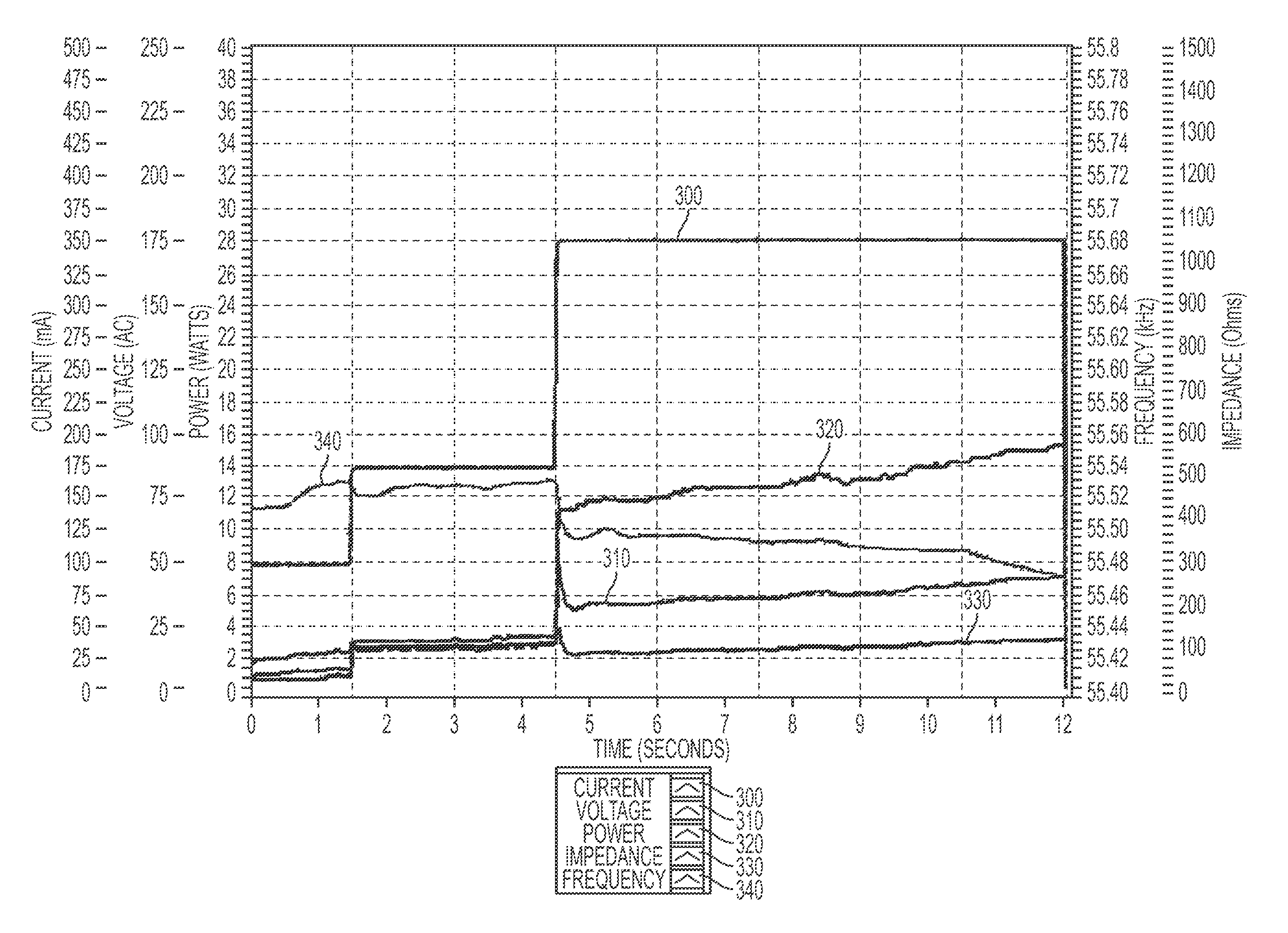
[0275]In abusive conditions, frequency, frequency slope, and current waveforms may deviate from normal operation may be generated while the ultrasonic instrument is constantly activated at a power level 5, where the jaws of the ultrasonic instrument were opened for 1 second, then closed for 1 second and repeated for 17 cycles.

[0276]When an ultrasonic instrument is activated multiple times directly against the pad, the characteristic frequency slope waveform in a first region before the generator saturates becomes less negative than in a second after the generator saturates due, in large part, to the system efficiency...


PUM


Abstract

Various embodiments are directed to an apparatus and method of driving an end effector coupled to an ultrasonic drive system of a surgical instrument. The method comprises generating at least one electrical signal. The at least one electrical signal is monitored against a first set of logic conditions.

Description

CROSS REFERENCE TO RELATED APPLICATIONS[0001]This application claims the benefit of U.S. Provisional Patent Application Ser. No. 61 / 250,217, filed Oct. 9, 2009 and entitled “A Dual Bipolar and Ultrasonic Generator for Electro-Surgical Instruments,” which is hereby incorporated by reference in its entirety.[0002]This application also is a continuation-in-part of co-pending U.S. patent application Ser. No. 12 / 503,775, filed Jul. 15, 2009, now U.S. Pat. No. 8,058,771, entitled “Ultrasonic Device for Cutting and Coagulating with Stepped Output,” which claims the benefit under Title 35, United States Code §119(e), of (1) U.S. Provisional Patent Application Ser. No. 61 / 086,619, filed Aug. 6, 2008 and entitled “Ultrasonic Device for Cutting and Coagulating with Stepped Output” and (2) U.S. Provisional Patent Application Ser. No. 61 / 188,790, filed Aug. 13, 2008 and entitled “Ultrasonic Device for Cutting and Coagulating with Stepped Output,” each of which is hereby incorporated by reference...

Claims


Application Information

Patent Timeline
IPC IPC(8): H01L41/09B06B1/02A61B17/32A61B18/00A61B5/00A61B5/053A61B17/00
CPCA61B17/320092B06B1/0284A61B5/053A61B5/4836A61B2017/00176A61B2018/00303B06B2201/76A61B2017/00026A61B2018/00875A61B18/1206A61B18/1445A61B2017/320095A61B2017/320093A61B2017/320094A61B2018/00589A61B2017/00084A61B2017/00973A61B2018/00601A61B2018/0063A61B2018/00666A61B2018/00791A61B2018/00845A61B2018/00994A61B17/320068A61N7/00G05B15/02A61B18/14A61B2017/00203A61B2018/00005A61N7/02
Inventor MESSERLY, JEFFREY D.WIENER, EITAN T.NOYES, BRIAN T.ALDRIDGE, JEFFREY L.GIORDANO, JAMES R.ABBOTT, DANIEL J.MILLER, MATTHEW C.PRICE, NATHAN J.PRICE, DANIEL W.
Owner CILAG GMBH INT
Why Eureka
Try Eureka