Collapsible substructure for a mobile drilling rig

a mobile drilling rig and substructure technology, applied in mining structures, building repairs, foundation engineering, etc., can solve the problems of significant impact on the overall cost of drilling operations, and the amount of time that may be needed to perform operations,

Active Publication Date: 2015-07-28
NAT OILWELL VARCO LP
View PDF122 Cites 35 Cited by
  • Summary
  • Abstract
  • Description
  • Claims
  • Application Information

AI Technical Summary

Benefits of technology

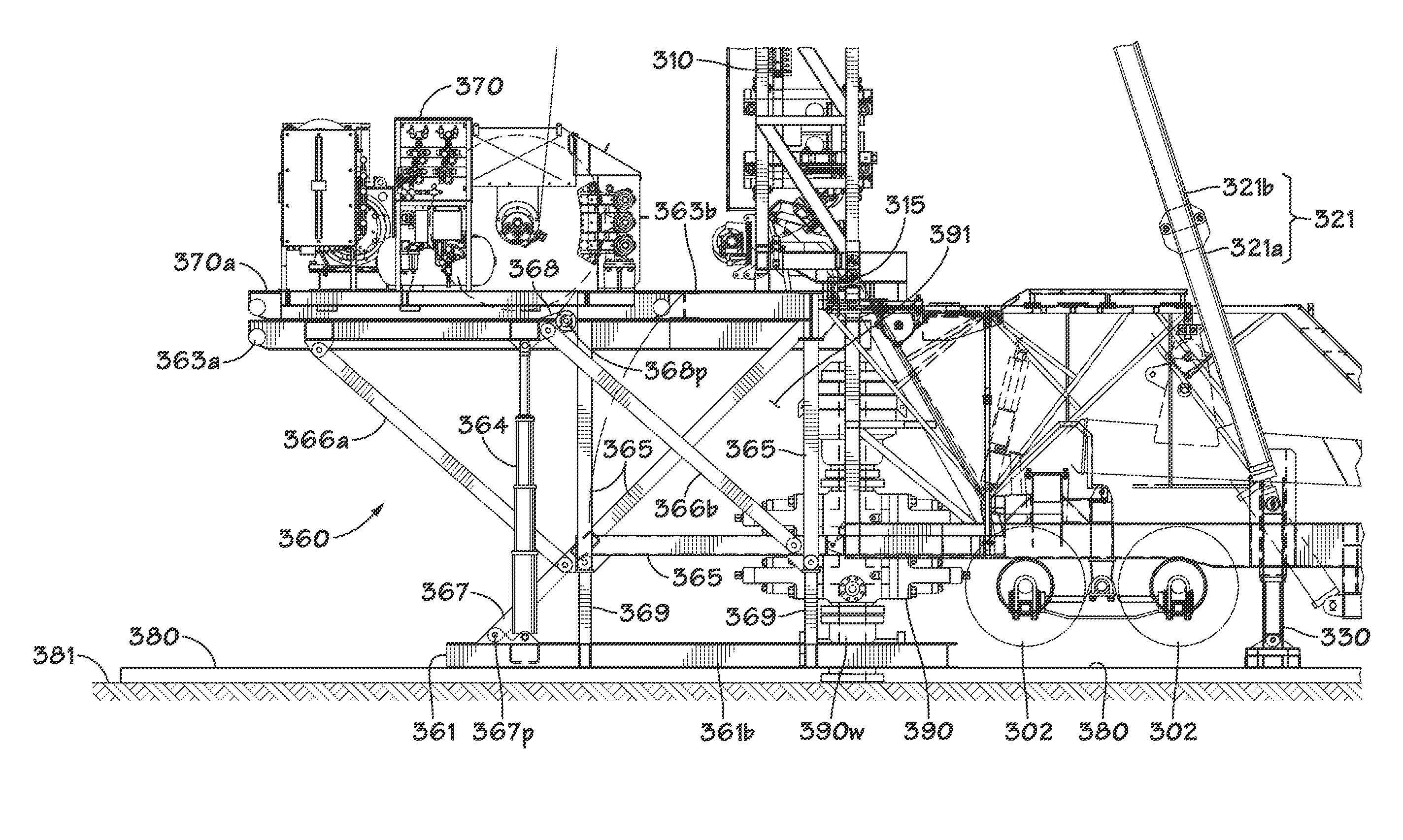
[0020]In yet another illustrative embodiment, a method is disclosed that includes, among other things, positioning a drawworks on a raisable floor of a drilling rig substructure, the raisable floor being positioned in a lowered transportation position wherein a height level of an upper surface of the raisable floor is lower than a height level of an upper surface of a fixed drill floor of the drilling rig substructure. The disclosed method further includes moving the drilling rig substructure with the drawworks positioned on the raisable floor to a drilling site, positioning the drilling rig substructure adjacent to a wellbore location, and raising the raisable floor to an operating position so as to position the drawworks adjacent to the fixed drill floor and at an operating height above a base of the drilling rig substructure.

Problems solved by technology

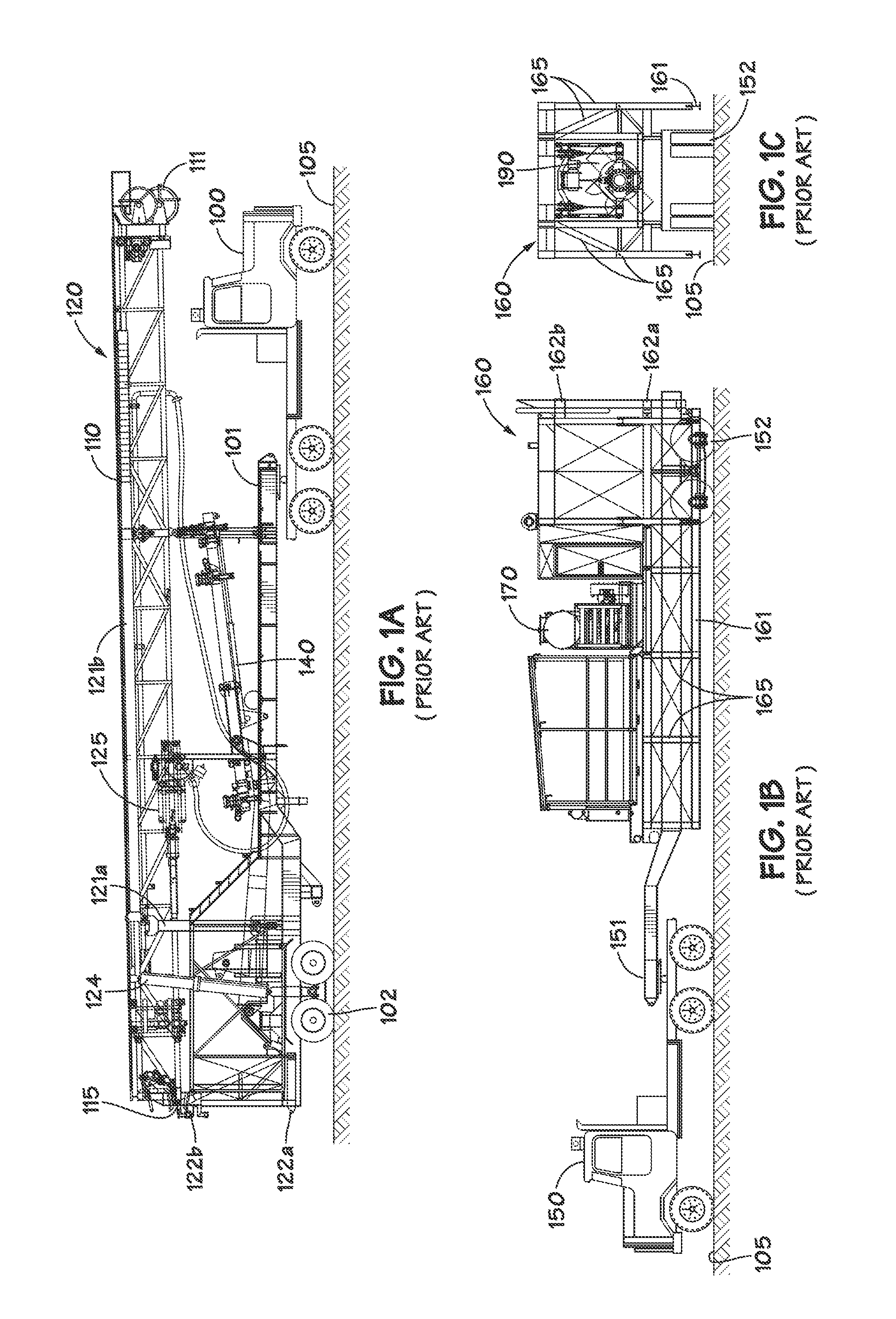
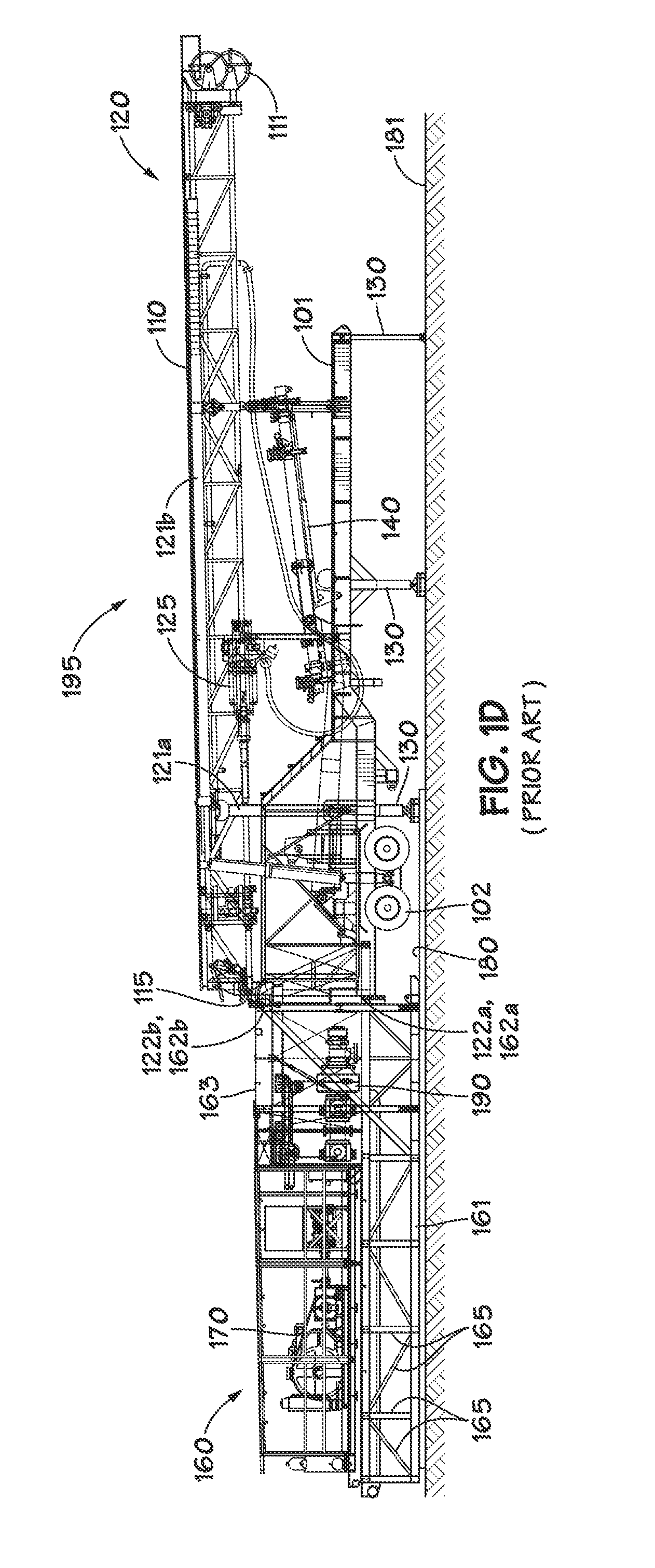
However, the relative positioning of the various slant rig components during drilling operations can lead to certain problems and / or inefficiencies during highway and / or road transportation of the slant rig components between oilfield sites, assembly and erection of the slant rig and movement of the assembled slant rig between adjacent wellbores during pad drilling.
As may be appreciated, the requirement that a crane be used during these stages can have a significant impact on the overall cost of the drilling operation, as well as the amount of time that may be needed to perform the operations.

Method used


Image

  • Collapsible substructure for a mobile drilling rig
  • Collapsible substructure for a mobile drilling rig
  • Collapsible substructure for a mobile drilling rig

Examples


Embodiment Construction

[0045]Various illustrative embodiments of the present subject matter are described below. In the interest of clarity, not all features of an actual implementation are described in this specification. It will of course be appreciated that in the development of any such actual embodiment, numerous implementation-specific decisions must be made to achieve the developers' specific goals, such as compliance with system-related and business-related constraints, which will vary from one implementation to another. Moreover, it will be appreciated that such a development effort might be complex and time-consuming, but would nevertheless be a routine undertaking for those of ordinary skill in the art having the benefit of this disclosure.

[0046]The present subject matter will now be described with reference to the attached figures. Various systems, structures and devices are schematically depicted in the drawings for purposes of explanation only and so as to not obscure the present disclosure ...


PUM


Abstract

Generally, the present disclosure is directed to a collapsible substructure of a mobile drilling rig. In one illustrative embodiment, a drilling rig substructure is disclosed that includes a base having a fixed drill floor mounted thereon, wherein an upper surface of the fixed drill floor is positioned at an operating height above the base for performing drilling operations at a wellbore location of a drilling site. Furthermore, a raisable floor is also included that is adapted to be positioned in a lowered transportation position for transportation of the substructure to the drilling site and raised to an operating position adjacent to the fixed drill floor for performing drilling operations, wherein a height level of an upper surface of the raisable floor is lower than a height level of the upper surface of the fixed drill floor when the raisable floor is positioned in the lowered transportation position.

Description

BACKGROUND[0001]1. Field of the Disclosure[0002]The present subject matter is generally directed to mobile drilling rig assemblies, and, in particular, to the use of a collapsible drilling rig substructure to facilitate both highway transportation and drilling site movement of a mobile drilling rig.[0003]2. Description of the Related Art[0004]In many land-based oil and gas drilling operations, drilling rigs are delivered to an oilfield drilling site by transporting the various components of the drilling rig over roads and / or highways. Typically, the various drilling rig components are transported to the drilling site on one or more truck / trailer combinations, the number of which may depend on the size, weight and complexity of the rig. Once at the drilling site, the components are then assembled, and the drilling rig mast is erected to an appropriate operating position. In many applications, the drilling rig mast is raised to a substantially vertical operating position so that drill...

Claims


Application Information

Patent Timeline
Patent Type & Authority Patents(United States)
IPC IPC(8): B66C23/06E21B15/00E21B15/04
CPCE21B15/00E21B15/003E21B15/04E21F15/04E21B7/02E21B15/006E21B7/023
Inventor KONDUC, KAMERON WAYNETHIESSEN, JAY JOHN
Owner NAT OILWELL VARCO LP
Why Eureka
Try Eureka