Castellated optical fiber cable retention structure

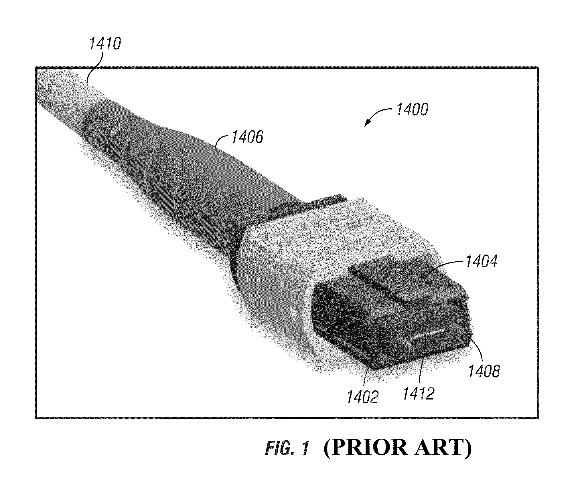
a technology of optical fiber and retention structure, applied in the field of optical fiber connectors, can solve the problems of increasing connector insertion loss and reflection loss, inability to hold tolerance well, and polymerization also susceptible to creep and thermal expansion/contraction, and achieves low environmental sensitivity, high reliability, and low cost

Inactive Publication Date: 2015-07-28
SENKO ADVANCED COMPONENTS
View PDF10 Cites 7 Cited by
  • Summary
  • Abstract
  • Description
  • Claims
  • Application Information

AI Technical Summary

Benefits of technology

[0015]The present invention provides a fiber cable retention structure (e.g., in an optical fiber connector), which overcomes many of the drawbacks of the prior art fiber cable retention structures. The fiber cable retention structure in accordance with the present invention is designed to accommodate large variations in the relatively soft exterior layer(s) of an optical fiber cable, which provides ease of use and high reliability with low environmental sensitivity, and which can be fabricated at low cost.
[0016]In accordance with the present invention, the cable retention structure comprises at least a body defining a fiber cable clamping surface having castellations distributed along a direction parallel to the axis of the fiber cable. The castellated surface resembles a corrugated surface, and when provided at the inside wall of a groove, defines a series of alternating small and large cavities distributed along the axial direction. The small cavities are sized such that when the castellated surface is pressed against the buffer jacket exterior of the fiber cable, the small cavities will be able to clamp the fiber cable jacket within its full dimensional tolerance range. The large cavities are sized to provide sufficient clearance to accommodate the relatively soft material of the cable jacket which cannot be accommodated by the small cavities. The cable jacket is thus securely held by the retention structure to prevent slipping. Accordingly, fiber cables having buffer jackets with large dimensional variations can still be securely retained by the castellated retention structure in accordance with the present invention.
[0019]In another aspect of the present invention, the open structure of the cable retention structure lends itself to mass production processes such as stamping and extrusion, which are low cost, high throughput processes.
[0021]The cable retention structure in accordance with the present invention overcomes many of the deficiencies of the prior art, resulting in an optical fiber connector that accommodates large variations in the relatively soft external layer(s) of an optical fiber cable, which provides ease of use and high reliability with low environmental sensitivity, and which can be fabricated at low cost.

Problems solved by technology

These devices couple fibers in an end-to-end relationship, with the coupling being one source of light loss.
Physical contact avoids a trapped layer of air between two fibers, which increases connector insertion loss and reflection loss.
The injection molded structure inherently does not hold tolerance well.
Polymers are also susceptible to creep and thermal expansion / contraction over longer periods of time.
The epoxy shrinks upon curing, which leads to bending of the plastic ferrule.
Further, epoxy creeps over time, leading to pistoning or retracting of the optical fiber ends (which are pushed against the ends of adjoining fibers) within the holes in the ferrule under the applied axial bias of the spring-load in the connector.
This compromises the integrity of the surface contact interface of opposing fiber end faces.
These and other deficiencies result in poor resultant tolerance that is more to be desired for modern day optical fiber applications.
Currently, it is generally accepted that fiber connectors cost too much to manufacture and the reliability and loss characteristics are more to be desired.
It is noted that given the soft materials of the buffer jacket of an optical fiber cable, the overall outer diameter (O.D.) of the fiber cable does not have a tight dimensional tolerance.
Heretofore, retention structures for the fiber cable have not been designed to effectively accommodate the relatively large ±50 μm variation of the buffer jacket.

Method used


Image

  • Castellated optical fiber cable retention structure
  • Castellated optical fiber cable retention structure
  • Castellated optical fiber cable retention structure

Examples


Embodiment Construction

[0031]This invention is described below in reference to various embodiments with reference to the figures. While this invention is described in terms of the best mode for achieving this invention's objectives, it will be appreciated by those skilled in the art that variations may be accomplished in view of these teachings without deviating from the spirit or scope of the invention.

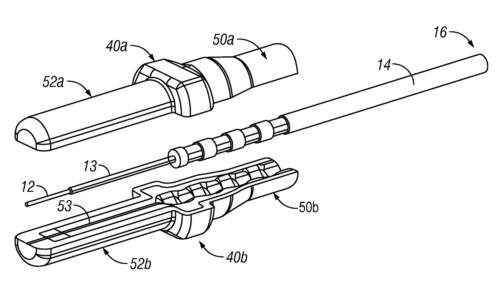
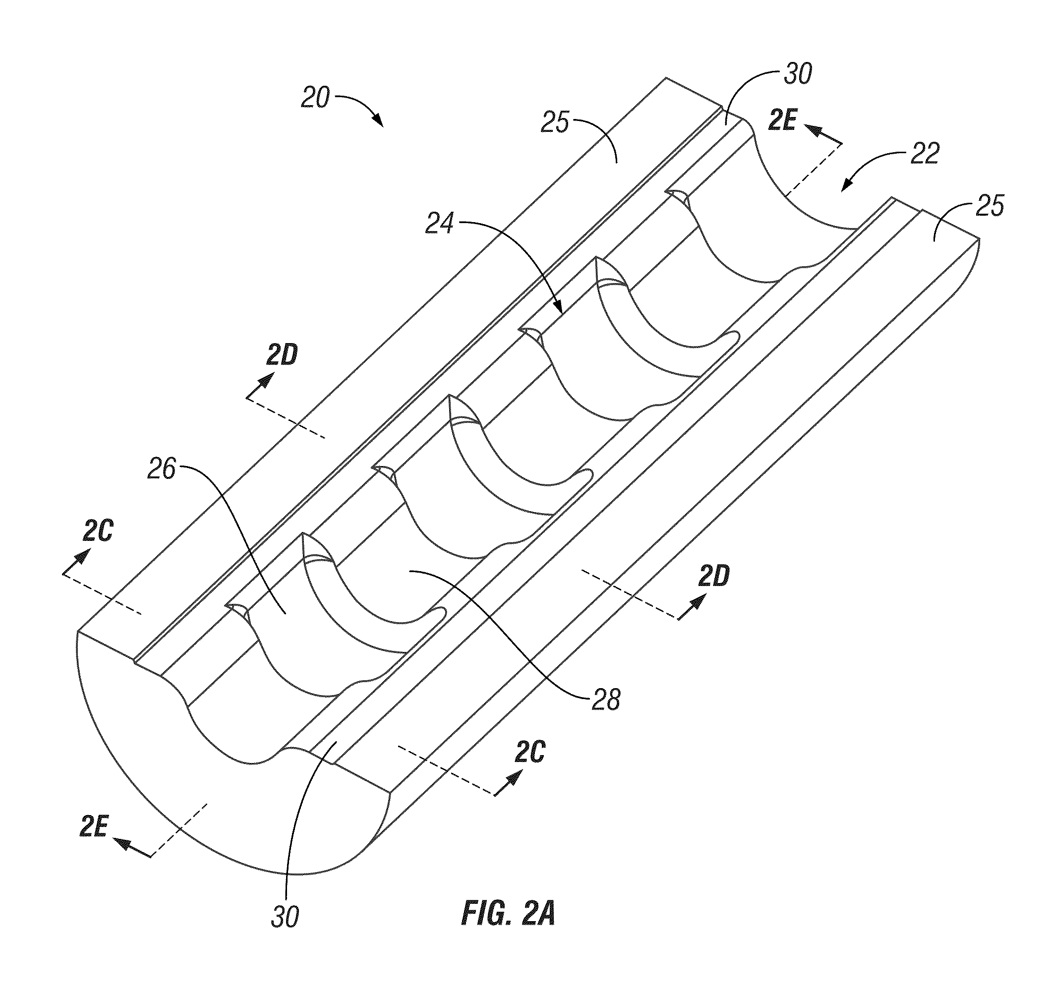
[0032]The present invention provides a fiber cable retention structure (e.g., in an optical fiber connector), which overcomes many of the drawbacks of the prior art fiber cable retention structures. The fiber cable retention structure in accordance with the present invention is designed to accommodate large variations in the relatively soft exterior layer(s) of an optical fiber cable, which provides ease of use and high reliability with low environmental sensitivity, and which can be fabricated at low cost. The fiber cable retention structure comprises at least a body defining a fiber cable clamping surfac...


PUM


Abstract

A cable retention structure defining a castellated fiber cable clamping surface. The castellated surface has a series of alternating small and large cavities distributed along the axial direction. The small cavities are sized such that when the castellated surface is pressed against the buffer jacket exterior of the fiber cable, the small cavities will be able to clamp the fiber cable jacket within its full dimensional tolerance range. The large cavities are sized to provide sufficient clearance to accommodate the relatively soft material of the cable jacket which cannot be accommodated by the small cavities. The cable jacket is securely held by the retention structure to prevent slipping. Accordingly, fiber cables having buffer jackets with large dimensional variations can still be securely retained by the castellated retention structure in accordance with the present invention.

Description

PRIORITY CLAIM[0001]This application claims the priority of U.S. Provisional Patent Application No. 61 / 554,938 filed on Nov. 2, 2011, which is fully incorporated by reference as if fully set forth herein. All publications noted below are fully incorporated by reference as if fully set forth herein.BACKGROUND OF THE INVENTION[0002]1. Field of the Invention[0003]The present invention relates to optical fiber connectors, in particular optical fiber cable retention structures in optical fiber connectors.[0004]2. Description of Related Art[0005]There are many advantages of transmitting light signal via optical fiber waveguides, and the use thereof is diverse. Single or multiple fiber waveguides may be used simply for transmitting visible light to a remote location. Complex telephony and data communication systems may transmit multiple specific optical signals. These devices couple fibers in an end-to-end relationship, with the coupling being one source of light loss. Precision alignment ...

Claims


Application Information

Patent Timeline
Patent Type & Authority Patents(United States)
IPC IPC(8): G02B6/00G02B6/44G02B6/38
CPCG02B6/4471G02B6/3887G02B6/387G02B6/3862G02B6/3865G02B6/3885G02B6/3888G02B6/38
Inventor CHEN, YANGHII, KING-FUMENGESHA, TEWODROSBOSCH, FREDMORGAN, CHRISVALLANCE, ROBERT RYAN
Owner SENKO ADVANCED COMPONENTS
Why Eureka
Try Eureka