Splitter

a technology of splitter and splitter, which is applied in the field of splitter, can solve the problems of deteriorating communication quality, affecting the reliability of the transmission system, and the inability to function in the branch line, so as to prevent the intensity of the communication signal from decreasing, and achieve robust communication

Inactive Publication Date: 2015-08-04
PANASONIC INTELLECTUAL PROPERTY MANAGEMENT CO LTD
View PDF15 Cites 4 Cited by
  • Summary
  • Abstract
  • Description
  • Claims
  • Application Information

AI Technical Summary

Benefits of technology

[0006]The present invention has been made in view of the above-described problems, and an object of the present invention is to provide a splitter that can prevent the intensity of a communication signal from decreasing considerably at branch points from a trunk line to branch lines in a power line and ensure robust communication.
[0008]According to the invention, there is an advantage in that considerable lowering of intensity of the communication signal at each branch point from the trunk line to the branch line in the power line can be prevented and robust communication can be ensured.

Problems solved by technology

Thus, with the PLC communication signal, signal reflection and loss occur at branch points from the trunk line to the branch lines in the power line, possibly leading to a deterioration in communication quality.
However, the noise filters (filter circuits) described in Patent Documents 1 and 2, while being able to reduce reflection of a communication signal at an open end and noise emitted from an electric apparatus, cannot function in branch lines to which PLC communication apparatuses are connected, since these noise filters do not pass the PLC communication signal.
Thus, even if these noise filters (filter circuits) are used, reflection or loss of the communication signal at the branch points from the trunk line to the branch lines in the power line cannot be reduced.
However, it is difficult for a general user to take measures to change the connection location of the filter circuit.

Method used


Image

  • Splitter
  • Splitter
  • Splitter

Examples


embodiment 1

[0019

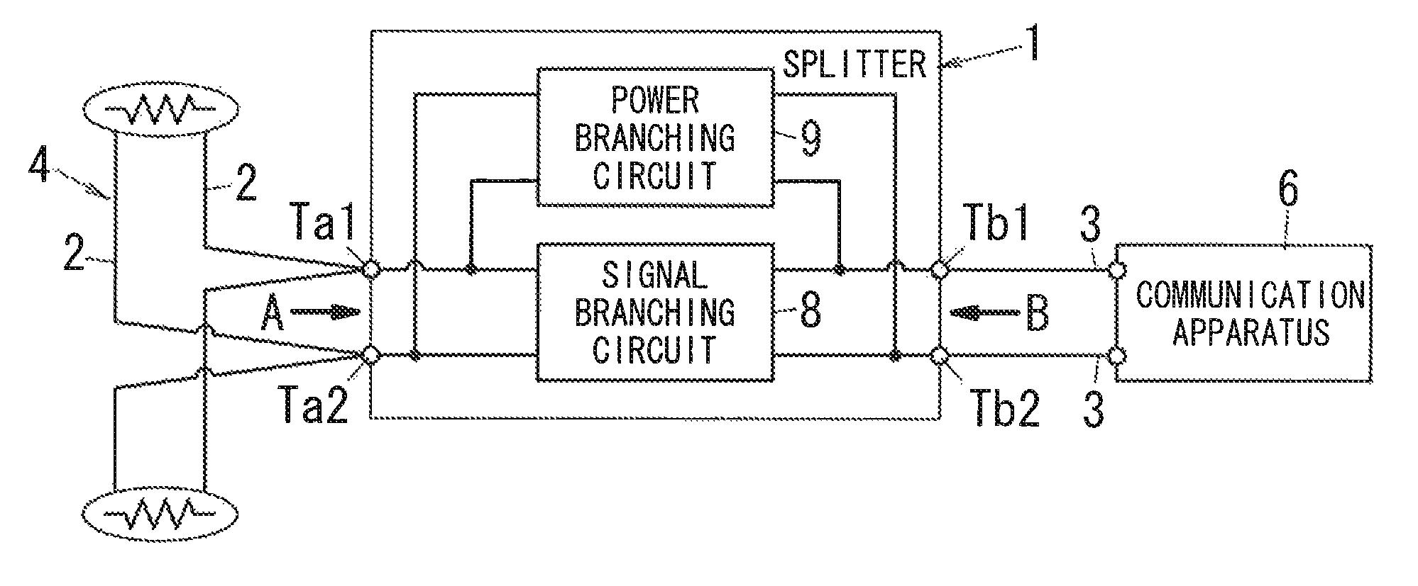
[0020]In the present embodiment, a case where, in an AC power distribution system in which AC power is distributed to an interior of a residence or the like as the distributed power, PLC communication apparatuses communicate by communication signals that are superimposed on the AC power distributed through a power line will be described as an example. A frequency band of the communication signal is set to a frequency band (10 kHz-450 kHz or 2 MHz-30 MHz, for example) in which a frequency that is sufficiently higher than the frequency (50 Hz or 60 Hz) of the AC power (commercial power) distributed through the power line is set as a lower limit.

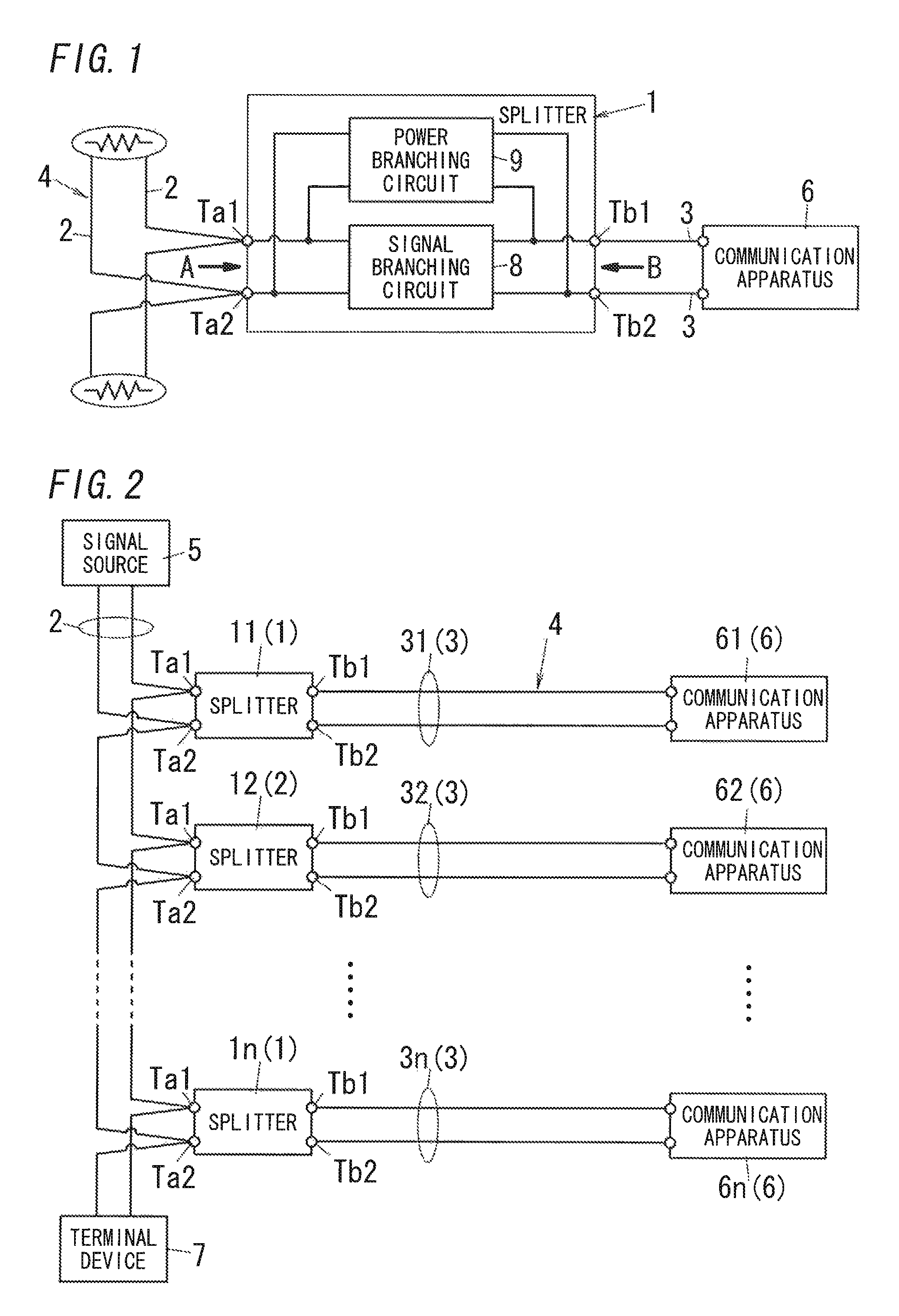
[0021]The power distribution system has, as shown in FIG. 2, a power line 4 that includes a trunk line 2 and a plurality of (n sets, here) branch lines 31, 32, . . . , 3n that are branched from the trunk line 2, and distributes the AC power through respective branch lines 31, 32, . . . , 3n from the trunk line 2. At one end of the trunk li...

embodiment 2

[0059

[0060]A splitter 1 of the present embodiment differs from the splitter 1 of Embodiment 1 in that the splitter 1 is used in a DC power distribution system in which DC power is distributed to an interior of a residence as the distributed power. In the present embodiment, a PLC communication apparatus 6 (see FIG. 6) communicates by superimposing the communication signal on the DC power distributed through a power line 4 (see FIG. 6). Hereinafter, constituent elements similar to Embodiment 1 are provided the same reference sign, and redundant description thereof will be omitted appropriately.

[0061]The DC power distribution system of the present embodiment includes, as shown in FIG. 6, a DC power supply 110 for outputting DC power and a DC distribution board 120 for distributing the output of the DC power supply 110 to the interior of a residence. The DC power supply 110 includes an AC / DC converter 111 for converting an AC supplied by a commercial power supply (not shown) to a DC, a...


PUM


Abstract

A splitter includes, in parallel between trunk terminals and branch terminals, a signal branching circuit that blocks distributed power and passes a PLC communication signal and a power branching circuit that blocks the communication signal and passes the distributed power. In the signal branching circuit, impedance viewed from the branch terminal side is matched with characteristic impedance of a power line and impedance viewed from the trunk terminal side is higher than impedance viewed from the branch terminal side, in the frequency band of the communication signal. In the power branching circuit, input / output impedance is set to be sufficiently higher than the impedance of the signal branching circuit viewed from the trunk terminal side, in the frequency band of the communication signal.

Description

TECHNICAL FIELD[0001]This invention relates to a splitter for branching a communication signal.BACKGROUND ART[0002]Conventionally, in the field of communication, power line communication (PLC) technology is known in which a communication signal in a predetermined frequency band is transmitted superimposed on distributed power using a power line as a transmission line. PLC is attracting attention as technology that enables easy construction of a network because there is no need to provide a dedicated communication line separately from the power line, since the power line for supplying electric power is also used as the transmission line for communication apparatuses to communicate with each other. Note that, in a case where the power line is a power line for AC power distribution, the frequency band of the communication signal is set to a frequency band that is sufficiently higher than the frequency of the AC power that is supplied through the power line.[0003]Incidentally, a power l...

Claims


Application Information

Patent Timeline
Patent Type & Authority Patents(United States)
IPC IPC(8): H04B3/00H04L25/00H04B3/56H04B3/54
CPCH04B3/54H04B3/56H04B2203/5425H04B2203/5483H04B2203/5491
Inventor YAMAMOTO, YASUKOTANABE, MITSURUMAEDA, MITSURUKUNIYOSHI, KENJI
Owner PANASONIC INTELLECTUAL PROPERTY MANAGEMENT CO LTD
Why Eureka
Try Eureka