Piezoelectric elastic wave deicing method

A piezoelectric elastic wave and piezoelectric vibrator technology, applied in the field of deicing the outer surface of outdoor equipment, to achieve low energy consumption, avoid the influence of wing strength and vibration characteristics, and small volume and weight

Active Publication Date: 2013-02-27
NANJING UNIV OF AERONAUTICS & ASTRONAUTICS
View PDF5 Cites 19 Cited by
  • Summary
  • Abstract
  • Description
  • Claims
  • Application Information

AI Technical Summary

Problems solved by technology

Furthermore, with the development of new aircraft structural materials, a large number of polymer composite materials have been applied to helicopter rotor blades as a lightweight high-corrosion coating layer, and the electrothermal deicing method contradicts this development trend

Method used


Image

  • Piezoelectric elastic wave deicing method
  • Piezoelectric elastic wave deicing method
  • Piezoelectric elastic wave deicing method

Examples


Embodiment 1

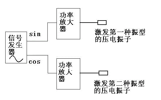
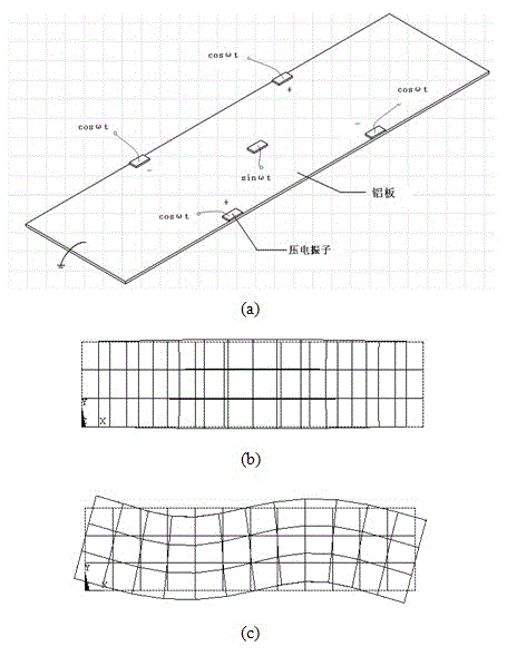
[0023] In the piezoelectric elastic wave deicing method of the present invention, the signal generator generates two alternating voltages with a phase difference of π / 2, which are respectively amplified by two power amplifiers and applied to piezoelectric vibrators of two different vibration modes (the first on the piezoelectric vibrator of the first mode and the piezoelectric vibrator of the second mode). The piezoelectric vibrator of the first vibration mode is selected as the first-order in-plane longitudinal stretching vibration mode E1 of the deiced surface, and the piezoelectric vibrator of the second vibration mode is selected as the second-order out-of-plane bending vibration mode B2. figure 2 (a) shows the first-order in-plane longitudinal stretching vibration mode E1 based on the deiced surface ( figure 2 (b)) and the second out-of-plane bending vibration mode B2 ( figure 2 (c)) Schematic illustration of traveling wave-like elastic wave generation. In order to e...

Embodiment 2

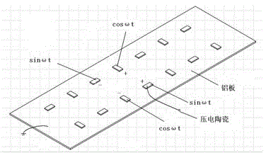
[0026]In the piezoelectric elastic wave deicing method of the present invention, the signal generator generates two alternating voltages with a phase difference of π / 2, which are respectively amplified by two power amplifiers and applied to piezoelectric vibrators of two different vibration modes (the first on the piezoelectric vibrator of the first mode and the piezoelectric vibrator of the second mode). The piezoelectric vibrator of the first vibration mode is selected as the B10 vibration mode of the surface to be deiced, and the piezoelectric vibrator of the second vibration mode is selected as the B06 vibration mode. In vibration mechanics, a double subscript (mn) is usually used to describe the natural mode shape of a two-dimensional structure, and the positive integers m and n represent the number of nodal lines of the mode shape parallel to the x and y axis directions, respectively. Thus, B10 means that the mode forms one wave in the y-direction, and B06 means that the...


PUM


Abstract

The invention discloses a piezoelectric elastic wave deicing method. A signal generator generates two paths of alternating voltage which have phi/2 phase difference and are same in frequency, the two paths of alternating voltage are respectively amplified by two power amplifiers, two piezoelectric units which are attached on the inner surface of an aircraft skin are used for exciting two piezoelectric vibrators in different vibration type on the skin, i.e. the vibrations of the first vibration type of piezoelectric vibrators and the second vibration type of piezoelectric vibrators, under the excitation of the same driving frequency, the first vibration type of piezoelectric vibrators and the second vibration type of piezoelectric vibrators generate two vibration modes, i.e. longitudinal vibration or bending vibration, the two vibration modes are stacked on elastic waves formed on the aircraft skin, the elastic waves are similar to traveling waves, the shearing force is generated on the attaching interface of an ice layer, the ice layer is forced to strip from the skin under the action of the shearing force, and then the aircraft surface is deiced. The piezoelectric elastic wave deicing method has the advantages that the energy consumption is low, the power consumption is low, the piezoelectric elastic wave deicing method is compatible with an aircraft avionics system and does not require single power supplying, and the continuous operation is realized.

Description

technical field [0001] The invention belongs to the field of deicing the outer surface of outdoor equipment, and is suitable for deicing the surface of aircraft, in particular to a piezoelectric elastic wave deicing method. Background technique [0002] Although technological advances have made aviation safer, massive icing on aircraft wings has become one of the most challenging issues in the aviation industry. At a certain altitude, the highly supercooled water droplets in the clouds exist in an unstable liquid form. When the plane passes by, the water droplets will quickly gather and solidify on the fuselage to become an ice layer. The icing of the aircraft not only deteriorates the aerodynamic performance, increases the drag force, and reduces the lift force, leading to a stall (that is, the lift force of the aircraft is rapidly lower than the gravity force of the aircraft, and the aircraft falls rapidly), but also causes problems such as reduced engine power, unclear vi...

Claims


Application Information

Patent Timeline
Patent Type & Authority Applications(China)
IPC IPC(8): B64D15/16H02N2/00
Inventor 杨颖金家楣朱春玲
Owner NANJING UNIV OF AERONAUTICS & ASTRONAUTICS
Why Eureka
Try Eureka