
X-ray imaging apparatus and method of operating the same

a technology of x-ray imaging and x-ray, which is applied in the measurement of radiation intensity, instruments, x/gamma/cosmic radiation, etc., can solve the problems of loss of x-rays, difficult to obtain high-quality image data, and deterioration of image data in each line, so as to prevent deterioration of image data, shorten the time for flushing operation, and improve the effect of quality

Active Publication Date: 2015-08-11
VIEWORKS
View PDF24 Cites 4 Cited by
  • Summary
  • Abstract
  • Description
  • Claims
  • Application Information

AI Technical Summary

Benefits of technology

This approach reduces X-ray loss and ensures high-quality image data by completing the flush operation before exposure, even with non-synchronized X-ray radiation, and allows for a single system setup without separate interface equipment, enhancing user convenience and X-ray detection efficiency.

Problems solved by technology

However, when using a passive line trigger type X-ray generator which radiates X-rays by sending only an exposure request signal to the X-ray imaging apparatus, or a non-line trigger type X-ray generator which radiates X-rays without sending an exposure request signal to the X-ray imaging apparatus, loss of X-rays occurs due to time consumption upon changeover from the flush operation of the X-ray imaging apparatus to the exposure operation thereof, thereby making it difficult to obtain high quality image data.
Further, when the X-ray imaging apparatus performs the exposure operation without completing the flush operation for lines in some areas in order to reduce loss of X-rays, there is a problem of deterioration in image data in each line.
However, since the progressive flush method requires a relatively long time until the flush operation is completed, large amounts of X-rays can be lost when the progressive flush operation is applied to the passive line trigger type or the non-line trigger type.

Method used


Image

  • X-ray imaging apparatus and method of operating the same
  • X-ray imaging apparatus and method of operating the same
  • X-ray imaging apparatus and method of operating the same

Examples


Embodiment Construction

[0055]Exemplary embodiments of the present invention will now be described in detail with reference to the accompanying drawings. It should be noted that the drawings are not to precise scale and may be exaggerated in thickness of lines or size of components for descriptive convenience and clarity. Furthermore, the terms used herein are defined by taking functions of the present invention into account and can be changed according to user or operator's custom or intention. Therefore, definition of the terms should be made according to the overall disclosure set forth herein.

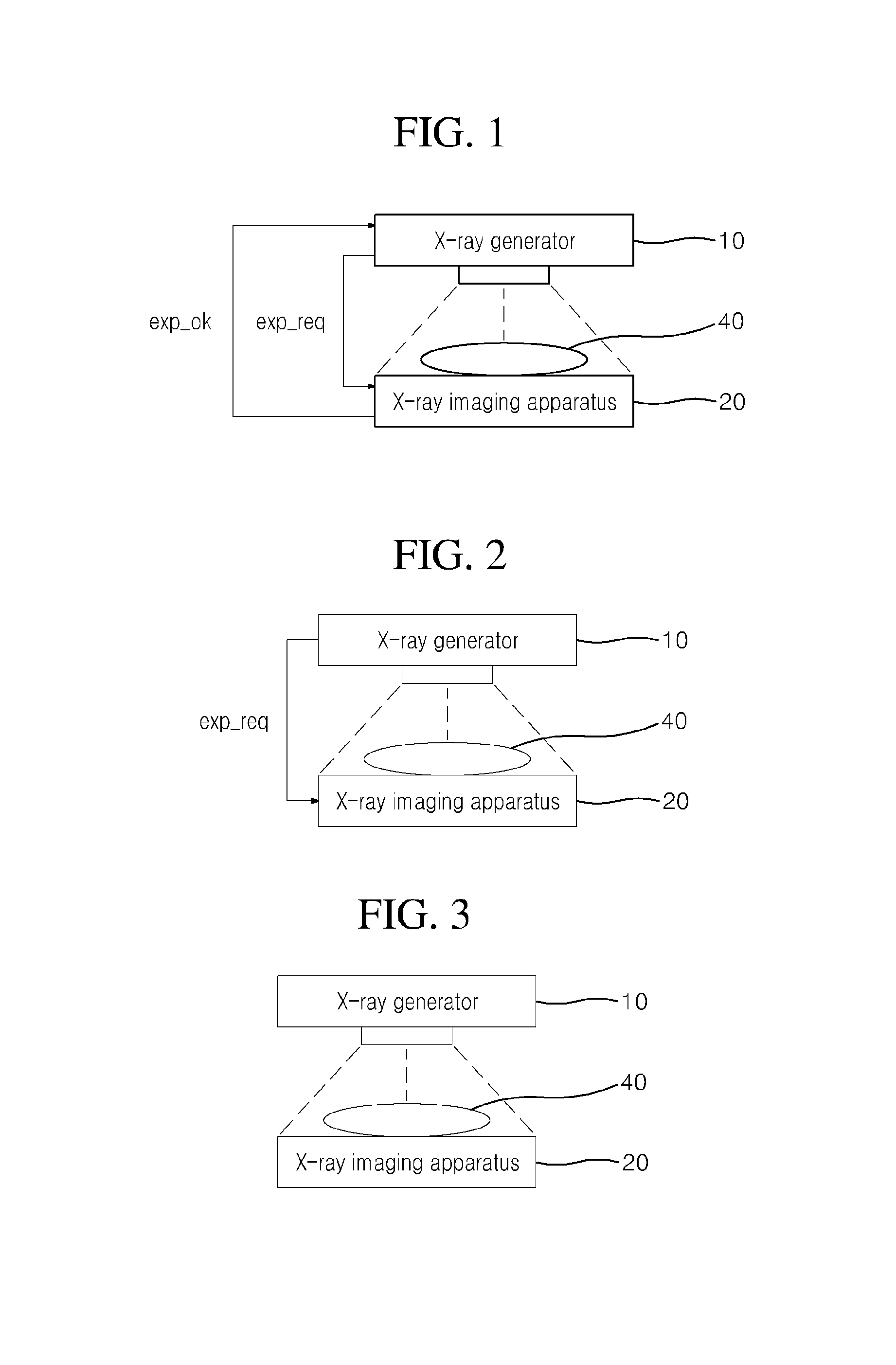
[0056]FIG. 1 shows X-ray radiation from an active line trigger type X-ray generator to an X-ray imaging apparatus and FIG. 2 shows X-ray radiation from a passive line trigger type X-ray generator to an X-ray imaging apparatus.

[0057]FIG. 3 shows X-ray radiation from an X-ray generator, which does not support a line trigger type operation, to an X-ray imaging apparatus.

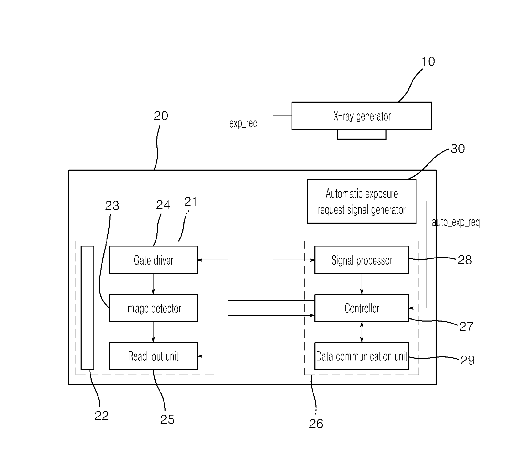
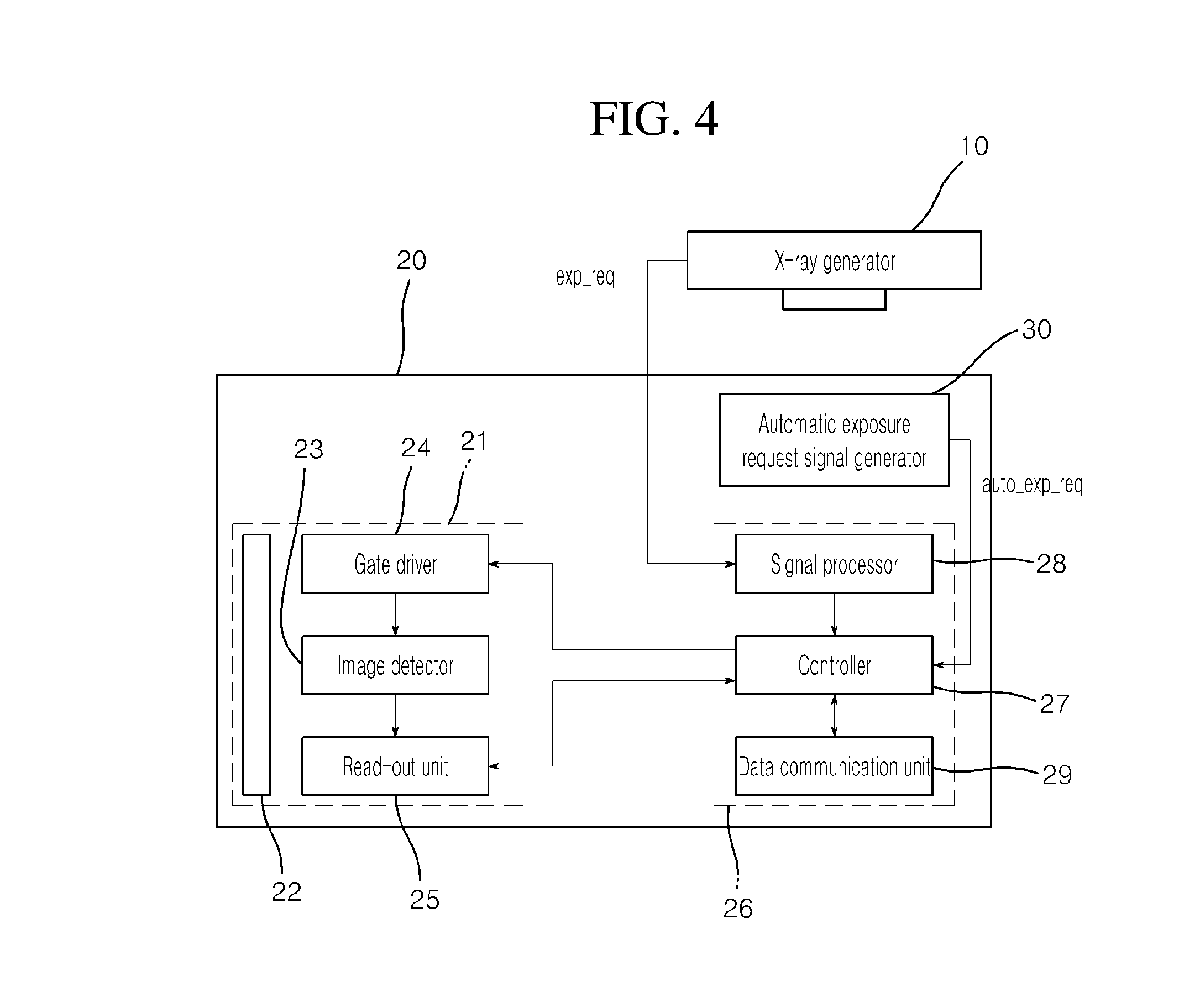
[0058]An X-ray generator 10 generates X-rays to...


PUM

PropertyMeasurementUnit
timeaaaaaaaaaa
electricaaaaaaaaaa
chargesaaaaaaaaaa

Abstract

An apparatus including a scintillator panel which absorbs X-rays radiated from an X-ray generator and converts the X-rays into visible light; an image detector including a plurality of pixels arranged in a matrix array and charging the plurality of pixels with electric charges proportional to intensity of the visible light converted by the scintillator panel; a gate driver which selects a line in the image detector and applies a drive signal to pixels in the selected line; an automatic exposure request signal generator which generates an automatic exposure request signal as a trigger signal informing of X-ray radiation through detection of X-rays radiated from the X-ray generator; and a controller which controls a time point of performing an exposure operation depending on a state of the drive signal applied to the pixels of the selected line in response to the automatic exposure request signal is disclosed.

Description

BACKGROUND[0001]1. Technical Field[0002]The present invention relates to an X-ray imaging apparatus and an operating method thereof. More particularly, the present invention relates to an X-ray imaging apparatus capable of photographing an X-ray image without loss of X-ray radiation even without an additional device for sharing a synchronizing signal with an X-ray generator, and a method of operating the same.[0003]2. Description of the Related Art[0004]Generally, an X-ray diagnosis system is constituted by an X-ray generator which generates X-rays and irradiates an object with the X-rays, and an X-ray imaging apparatus for photographing an X-ray image of the object.[0005]In such an X-ray diagnosis system, the X-ray imaging apparatus sequentially perform a flush operation for eliminating dark current from an image sensor in each line, an exposure operation for absorbing X-rays radiated from the X-ray generator, and a read-out operation for allowing the X-ray imaging apparatus to rea...

Claims


Application Information

Patent Timeline
Patent Type & Authority Patents(United States)
IPC IPC(8): G01N23/04G01T1/20G01T1/00A61B6/00
CPCG01T1/2018A61B6/4233A61B6/542G01N23/04G01T1/20184G01T1/247
Inventor SUNG, YONG HAKKIM, TAE GYUN
Owner VIEWORKS
Learn More