
Image forming apparatus with controlled fixing temperature, control method and storage medium

a technology of fixing temperature and control method, applied in the direction of electrographic process apparatus, instruments, optics, etc., can solve the problems of not being able to control power consumption, not being able to reduce power consumption in sufficient proportions, and reducing the power consumption of the image forming apparatus. , to achieve the effect of preventing degradation of print quality and reducing the power consumption of the image forming apparatus

Inactive Publication Date: 2015-08-11
CANON KK
View PDF15 Cites 3 Cited by
  • Summary
  • Abstract
  • Description
  • Claims
  • Application Information

AI Technical Summary

Benefits of technology

The present invention is a technique that reduces power consumption in an image forming apparatus while maintaining high print quality. It achieves this by controlling the amount of toner applied based on the temperature setting of the apparatus. By controlling the fixing temperature and toner application, the invention reduces power consumption and prevents degradation in print quality. Additionally, the invention can also reduce power rates by adjusting the fixing temperature based on power price information.

Problems solved by technology

It is well known that in an image forming apparatus adopting an electrophotographic method which forms a toner image on a recording material and thermally fixes the formed toner image on the recording material by a fixing device, the power consumption of the fixing device accounts for most of the power consumption of the image forming apparatus.
The above-described conventional technique, however, pays attention to only power consumption in the standby state, and performs no control of power consumption while an image forming (printing) operation is actually executed.
When the image forming apparatus executes print processing at a high frequency, it almost never shifts to the standby state (energy saving mode), and thus the above-described conventional technique may not sufficiently reduce the power consumption.
The above-described conventional technique, however, cannot perform such control.

Method used


Image

  • Image forming apparatus with controlled fixing temperature, control method and storage medium
  • Image forming apparatus with controlled fixing temperature, control method and storage medium
  • Image forming apparatus with controlled fixing temperature, control method and storage medium

Examples


first embodiment

[0025][First Embodiment]

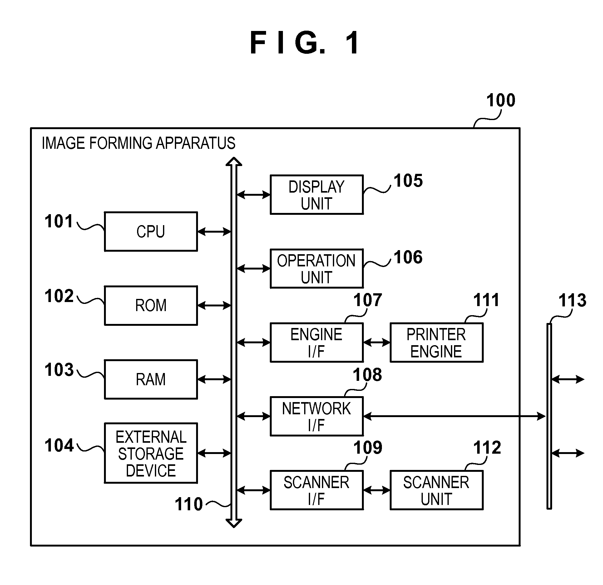
[0026]The first embodiment of the present invention will be described with reference to FIGS. 1 to 5. The present invention is applicable to an image forming apparatus adopting an electrophotographic method, such as a copying machine, multi-function peripheral (MFP), laser printer, or facsimile apparatus, regardless of whether the apparatus is a monochrome or multi-color apparatus. Note that in the first to third embodiments to be described below, an MFP including the scan function, print function, copy function, and transmission function will be exemplified as an image forming apparatus to which the present invention is applied. An MFP which can form a multi-color image on a recording material using developers (toners) of a plurality of colors (four colors of C, M, Y, and K) will also be explained by way of example.

[0027]

[0028]FIG. 1 is a block diagram showing the hardware configuration of an image forming apparatus 100 according to the first embodiment. The...

second embodiment

[0076][Second Embodiment]

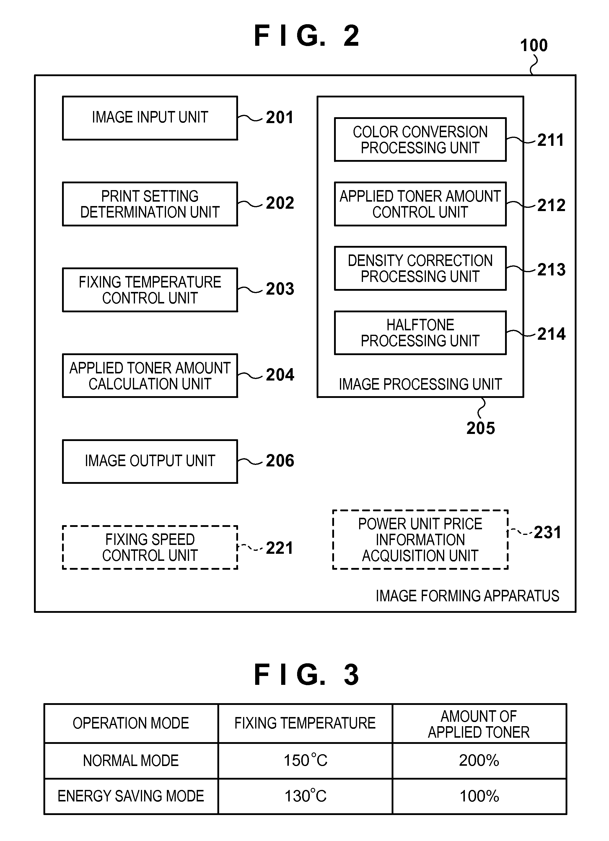
[0077]The image forming apparatus 100 according to the first embodiment reduces its power consumption while maintaining the print quality as high as possible by deciding the amount of fixable applied toner according to control of the fixing temperature of the fixing device (that is, control of power supply to the heater of the fixing device). If, for example, the apparatus sets the fixing temperature to the low set temperature in the energy saving mode, it correspondingly decides a small amount of applied toner within a range in which an image is fixable. If the apparatus decides a small amount of applied toner, a considerable influence is exerted on the print quality. This is because a reproducible color gamut becomes narrow as the amount of applied toner decreases.

[0078]On the other hand, it is well known that the amount of fixable applied toner at a given fixing temperature increases by lowering the image forming speed (print speed or fixing speed) of the...

third embodiment

[0099][Third Embodiment]

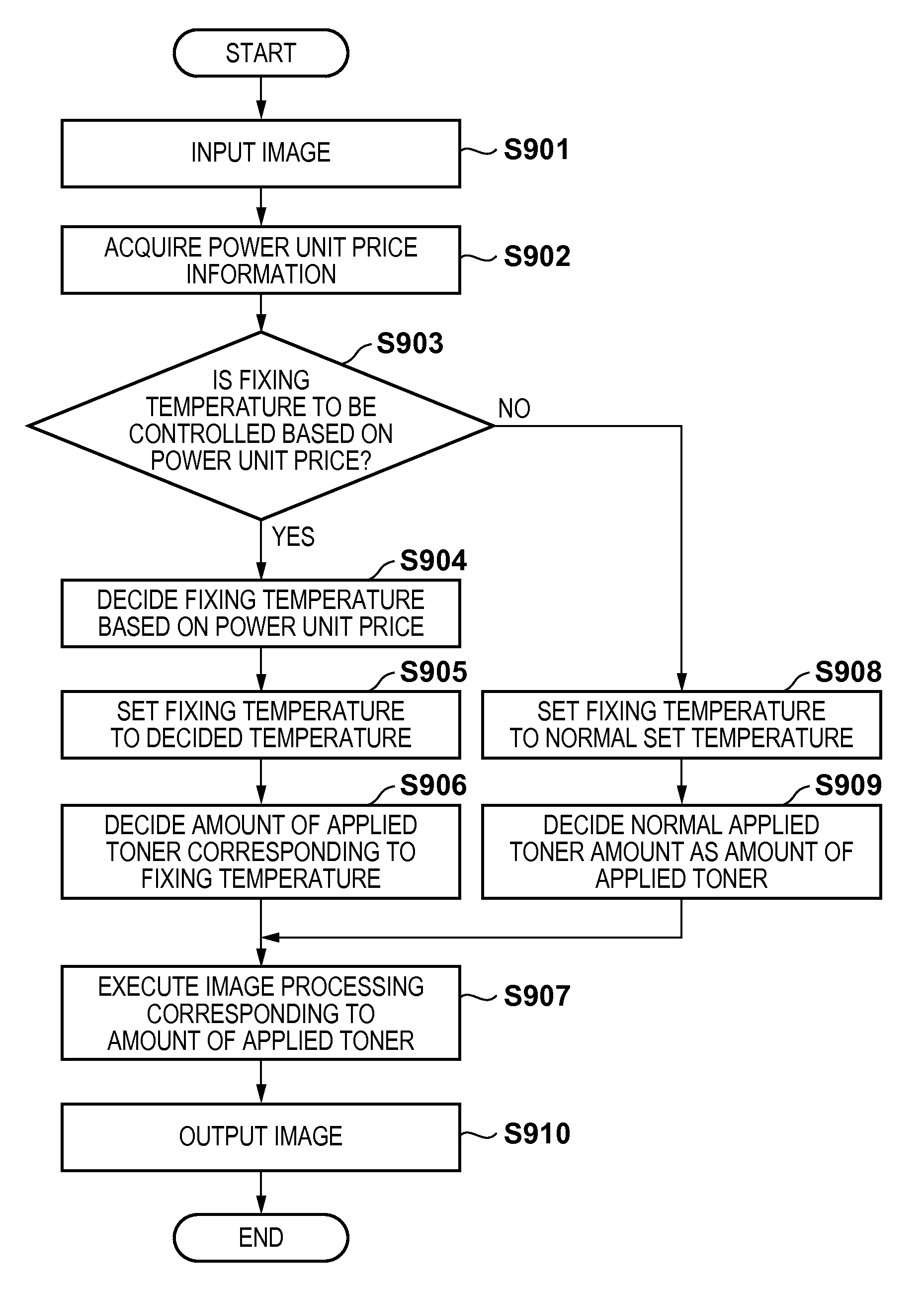
[0100]The image forming apparatus 100 according to the above-described first or second embodiment reduces its power consumption by controlling the fixing temperature of the fixing device, and also reduces degradation in print quality due to a decrease in amount of applied toner by deciding the amount of applied toner according to the fixing temperature.

[0101]In recent years, however, to level out power demands, power suppliers have introduced time-zone pricing which sets different electricity unit prices for different time zones. In this case, it is necessary to effectively reduce the power consumption according to a change in power price (that is, power supply) in addition to reducing the power consumption by the control operation described in the first or second embodiment.

[0102]To achieve this objective, in the third embodiment, a case in which power consumption is efficiently reduced by acquiring information indicating a power price from an external appar...


PUM


Abstract

An image forming apparatus according to an aspect of this invention controls a fixing temperature when a fixing device of a printer engine fixes an image on a recording material. More specifically, the image forming apparatus sets the fixing temperature to a value lower than that in a normal mode when printing an image in a power saving mode, and decides an amount of applied toner with which the fixing device can fix the image on the recording material at the set fixing temperature. Furthermore, the image forming apparatus generates print data corresponding to the decided amount of applied toner from input image data, and prints the image on the recording material based on the generated print data.

Description

BACKGROUND OF THE INVENTION[0001]1. Field of the Invention[0002]The present invention relates to an image forming apparatus, a control method therefor, and a storage medium.[0003]2. Description of the Related Art[0004]In recent years, in terms of improvement of environmental awareness and reduction of an electricity rate, it has been desired to reduce power consumption for general electric appliances. Therefore, image forming apparatuses having a power saving mode (energy saving mode) in which power consumption is lower than that in a normal operation mode are increasing.[0005]It is well known that in an image forming apparatus adopting an electrophotographic method which forms a toner image on a recording material and thermally fixes the formed toner image on the recording material by a fixing device, the power consumption of the fixing device accounts for most of the power consumption of the image forming apparatus. The following technique has thus been proposed. That is, when the...

Claims


Application Information

Patent Timeline
Patent Type & Authority Patents(United States)
IPC IPC(8): G03G15/20G03G15/00
CPCG03G15/205G03G15/5004G03G2215/2045
Inventor NAGAI, JUN
Owner CANON KK
Learn More