Coding apparatus and decoding apparatus

a decoding apparatus and coding technology, applied in the field of decoding apparatuses, can solve the problem of not being able to provide all essential applications with coded audio with sufficient quality, and achieve the effects of improving the bit efficiency of coded information, reducing the extreme increase in bit rate, and improving the audio quality of decoding signals

Active Publication Date: 2015-08-11
PANASONIC INTELLECTUAL PROPERTY MANAGEMENT CO LTD
View PDF18 Cites 6 Cited by
  • Summary
  • Abstract
  • Description
  • Claims
  • Application Information

AI Technical Summary

Benefits of technology

[0060]According to the present invention, it is possible to implement a coding apparatus and a decoding apparatus which suppress an extreme increase in a bit rate. For example, it is possible to improve the bit efficiency of coded information generated by the coding apparatus, and to improve the audio quality of a decoded signal obtained through decoding performed by the decoding apparatus.

Problems solved by technology

However, it is not possible to always provide all of essential applications with coded audio with sufficient quality.

Method used


Image

  • Coding apparatus and decoding apparatus
  • Coding apparatus and decoding apparatus
  • Coding apparatus and decoding apparatus

Examples


embodiment 1

[0083]First, descriptions for a coding apparatus will be given.

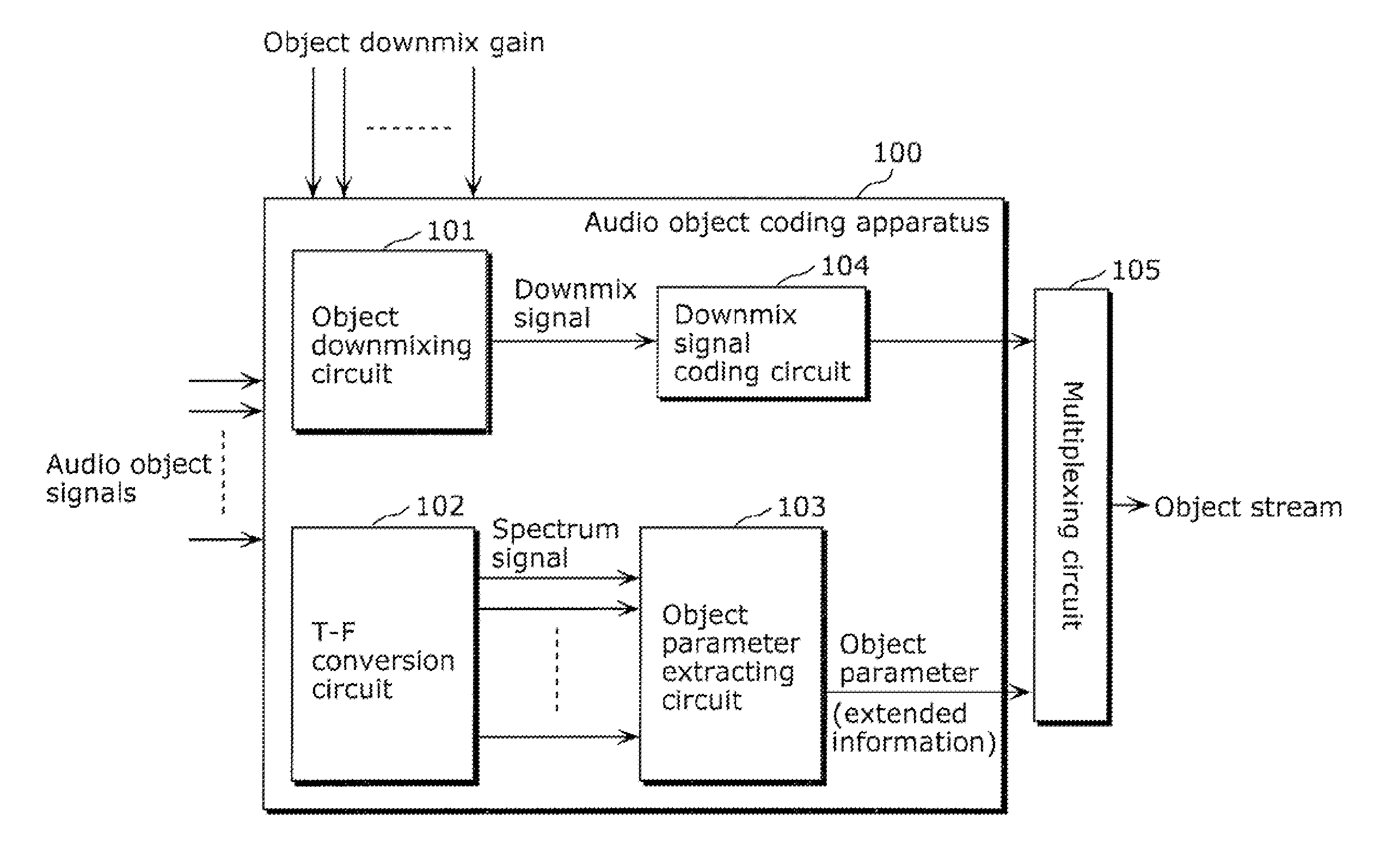
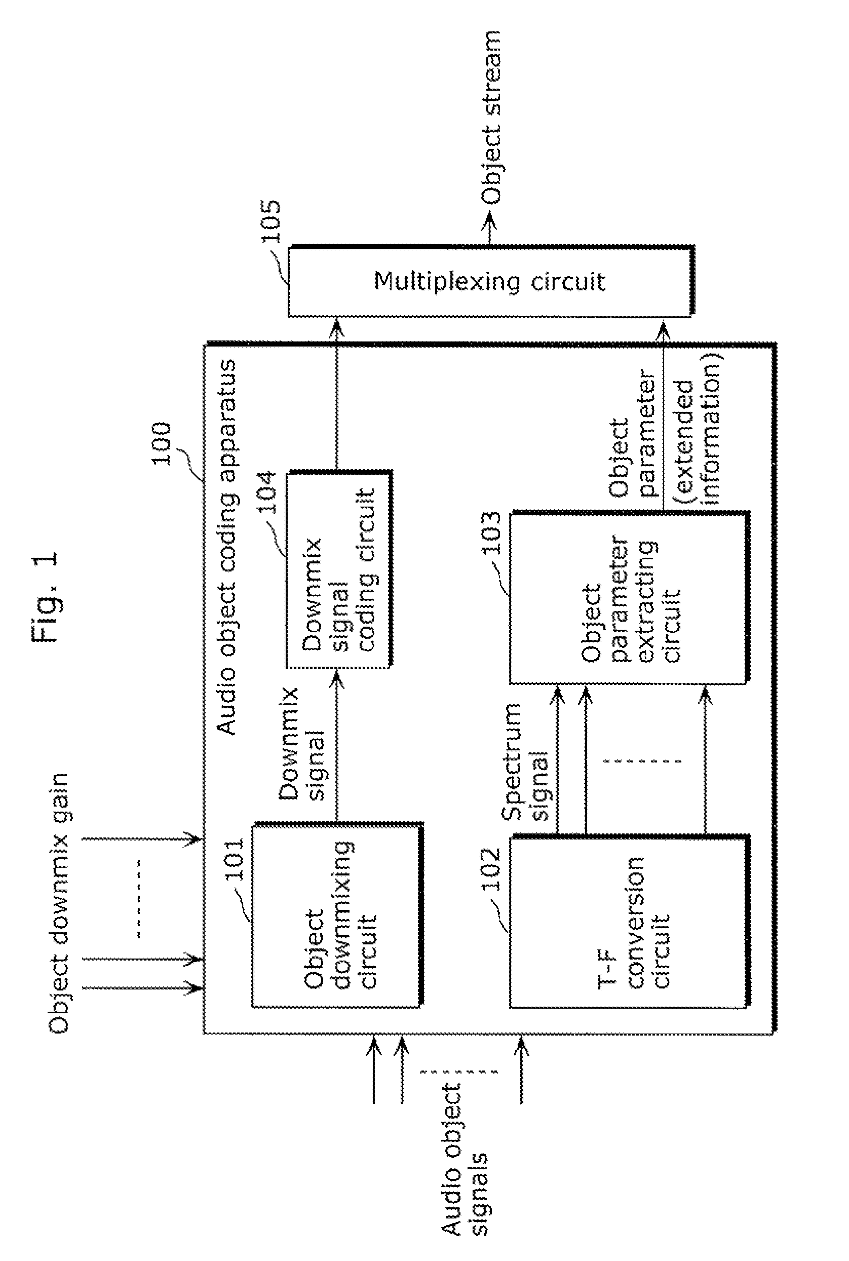
[0084]FIG. 4 is a block diagram which shows an example of a configuration of an audio object coding apparatus according to the present invention.

[0085]An audio object coding apparatus 300 shown in FIG. 4 includes: a downmixing and coding unit 301; a T-F conversion circuit 303; and an object parameter extracting unit 304. In addition, the audio object coding apparatus 300 includes a multiplexing circuit 309 in a subsequent stage.

[0086]The downmixing and coding unit 301 includes an object downmixing circuit 302 and a downmix signal coding circuit 310, downmixes provided audio object signals to reduce the number of channels, and codes the downmixed audio object signals.

[0087]More specifically, the object downmixing circuit 302 is provided with audio object signals and downmixes the provided audio object signals so as to be downmix signals which have the lower number of channels than the number of channels of the provided au...

embodiment 2

[0144]In the present embodiment, classifying audio object signals into classes is the same as Embodiment 1. Other parts; that is, the differences are described in the present embodiment.

[0145]In the present embodiment, object parameters (extended information) included in an audio object signal is extracted from the audio object signal in the frequency domain based on a reference class pattern. Then, all of the provided audio object signals are classified into several classes. Here, all of the audio object signals are classified into four types of classes including the reference class, by allowing two types of the temporal segments. Here, Table 1 indicates criteria for classifying an audio object signal i.

[0146]

TABLE 1Criteria ofClassificationDetails of ClassificationClassificationAThe case where each of the audioNtri = Vtrref and ifobject signals includes a temporalNtrref = , Tri(Ptrref) =segment and a position of temporalsegment of the pattern same as apattern of the reference clas...

embodiment 3

[0187]Next, in Embodiment 3, another aspect of the decoding apparatus which decodes a bitstream generated by the parametric object coding method which uses the technique of classification is described.

[0188]First, a general multi-channel decoder (spatial decoder) is explained for the purpose of comparison. FIG. 11 is a diagram which shows a general audio object decoding apparatus.

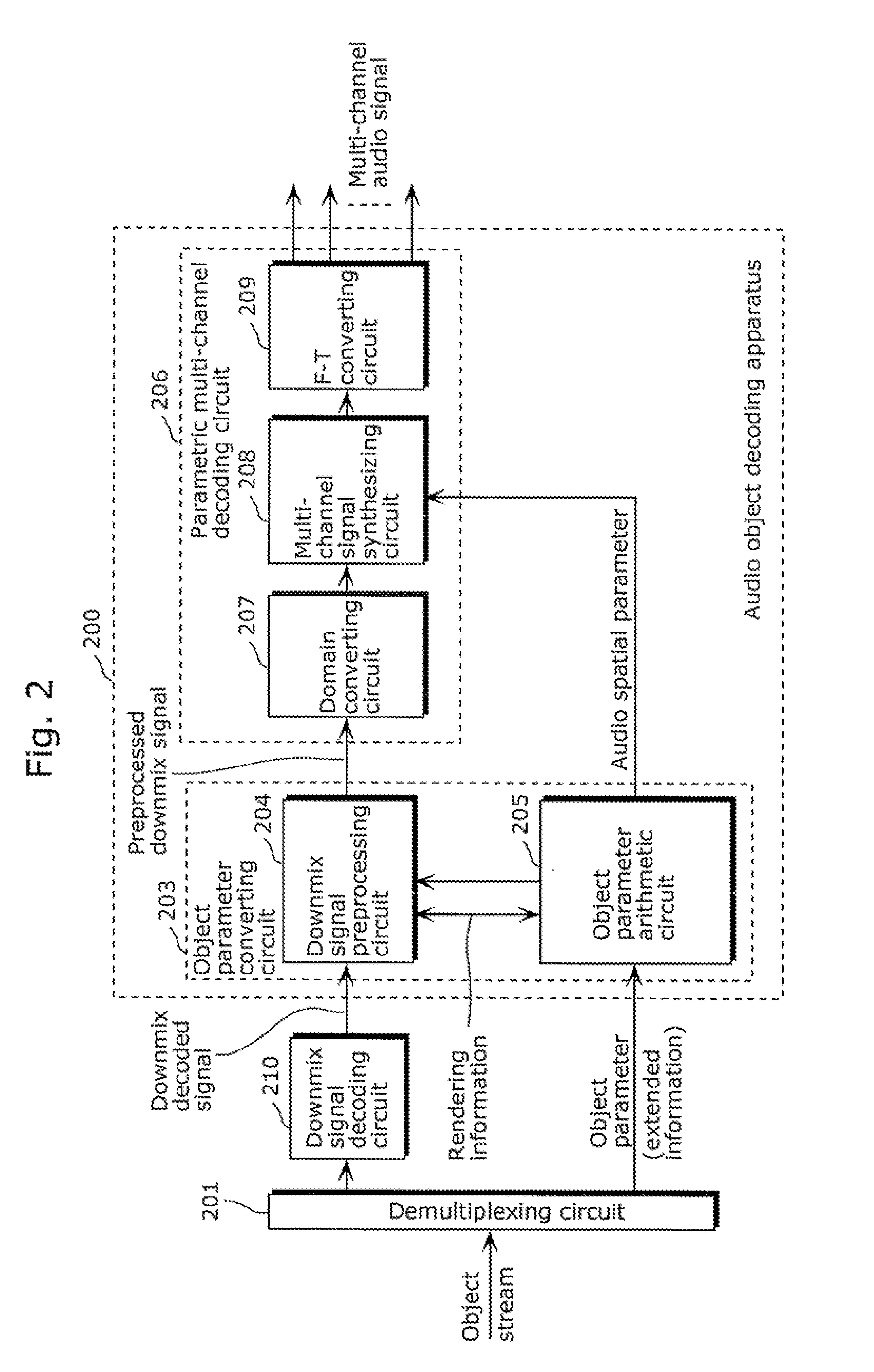
[0189]The audio object decoding apparatus shown in FIG. 11 includes a parametric multi-channel decoding circuit 700. Here, the parametric multi-channel decoding circuit 700 is a module in which a core module in the multi-channel signal synthesizing circuit 208 shown in FIG. 2 is generalized.

[0190]The parametric multi-channel decoding circuit 700 includes: a preprocess matrix arithmetic circuit 702; a post matrix arithmetic circuit 703; a preprocess matrix generating circuit 704; a postprocess matrix generating circuit 705; a linear interpolation circuits 706 and 707; and a reverberation component generating...


PUM


Abstract

A coding apparatus which suppresses an extreme increase in a bit rate, includes: a downmixing and coding unit (301) that downmixes audio signals that have been provided, to reduce the number of channels to be fewer than the number of the provided audio signals, and to code the downmix signals; an object parameter extracting unit (304) that extracts parameters indicating correlation between the audio signals; and a multiplexing circuit (309) that multiplexes the extracted parameters with the generated downmix coded signals. The object parameter extracting unit (304) includes: an object classifying unit (305) that classifies each of the provided audio signals into a predetermined one of types based on audio characteristics; and an object parameter extracting circuit (308) that extracts parameters using a temporal granularity and a frequency granularity each of which is determined for a corresponding one of the types.

Description

TECHNICAL FIELD[0001]The present invention relates to coding apparatuses and decoding apparatuses, and in particular to a coding apparatus that codes an audio object signal and a decoding apparatus that decodes the audio object signal.BACKGROUND ART[0002]As a method of coding an audio signal, a known typical method is, for example, a method of coding an audio signal by performing frame processing on the audio signal, using time segmentation with a temporally predetermined sample. In addition, the audio signal that is coded as described above and transmitted is decoded afterwards, and the decoded audio signal is reproduced by an audio reproduction system such as an earphone and speaker, or a reproduction apparatus.[0003]In recent years, technologies for enhancing convenience for a user of a reproduction apparatus by mixing a decoded audio signal with an external audio signal, or by performing rendering so as to reproduce a decoded audio signal from an arbitrary position such as up, d...

Claims


Application Information

Patent Timeline
Patent Type & Authority Patents(United States)
IPC IPC(8): H04R5/00G10L19/008G10L19/00
CPCG10L19/008H04S2420/03
Inventor ISHIKAWA, TOMOKAZUNORIMATSU, TAKESHICHONG, KOK SENGZHOU, HUAN
Owner PANASONIC INTELLECTUAL PROPERTY MANAGEMENT CO LTD
Why Eureka
Try Eureka