
Wireless communication method and apparatus based on channel function

a communication method and function technology, applied in the field of wireless communication, can solve the problems of high snr, restrictive transmission distance, and sensitive technology, and achieve the effect of optimal performan

Inactive Publication Date: 2015-08-11
ELECTRONICS & TELECOMM RES INST
View PDF5 Cites 11 Cited by
  • Summary
  • Abstract
  • Description
  • Claims
  • Application Information

AI Technical Summary

Benefits of technology

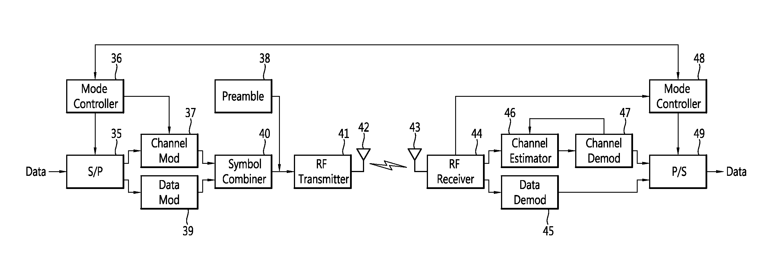
[0011]The present invention further provides a wireless communication method capable of increasing frequency efficiency based on a single transceiver, and an apparatus thereof.
[0016]According to the present invention, even when a single RF transceiver and a single antenna are used, higher frequency efficiency may be obtained as compared with a case of applying an existing modulation scheme. Further, since the present invention uses a preset channel function, the present invention may be insensitive to a channel environment and may represent an excellent performance even in a LOS environment such as a fixed point-to-point communication.
[0018]Moreover, according to the present invention, since a modulation rate is not fixed according to the number of antennas and the number of channel functions may be adaptively changed, an optimal performance may be implemented according to variation of the channel environment and reception sensitivity.

Problems solved by technology

However, since such a technology requires a high Signal to Noise Ratio (SNR), a transmission distance is restrictive and the technology is sensitive to a channel environment.
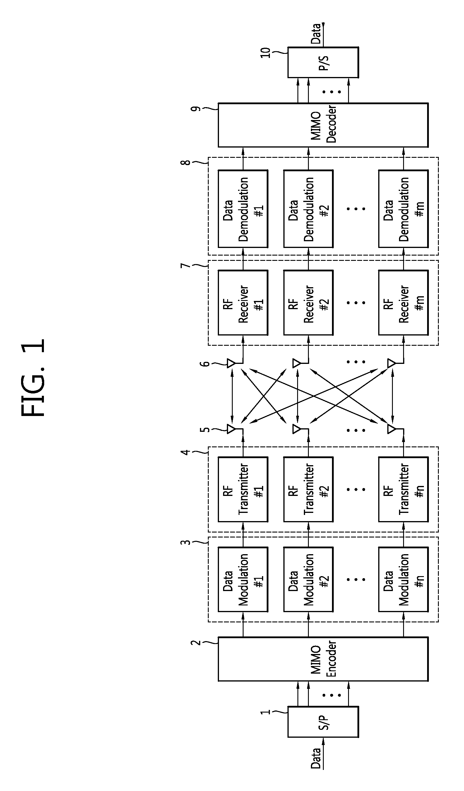
However, in this case, since N different signals interfere with other, a high SNR is required.
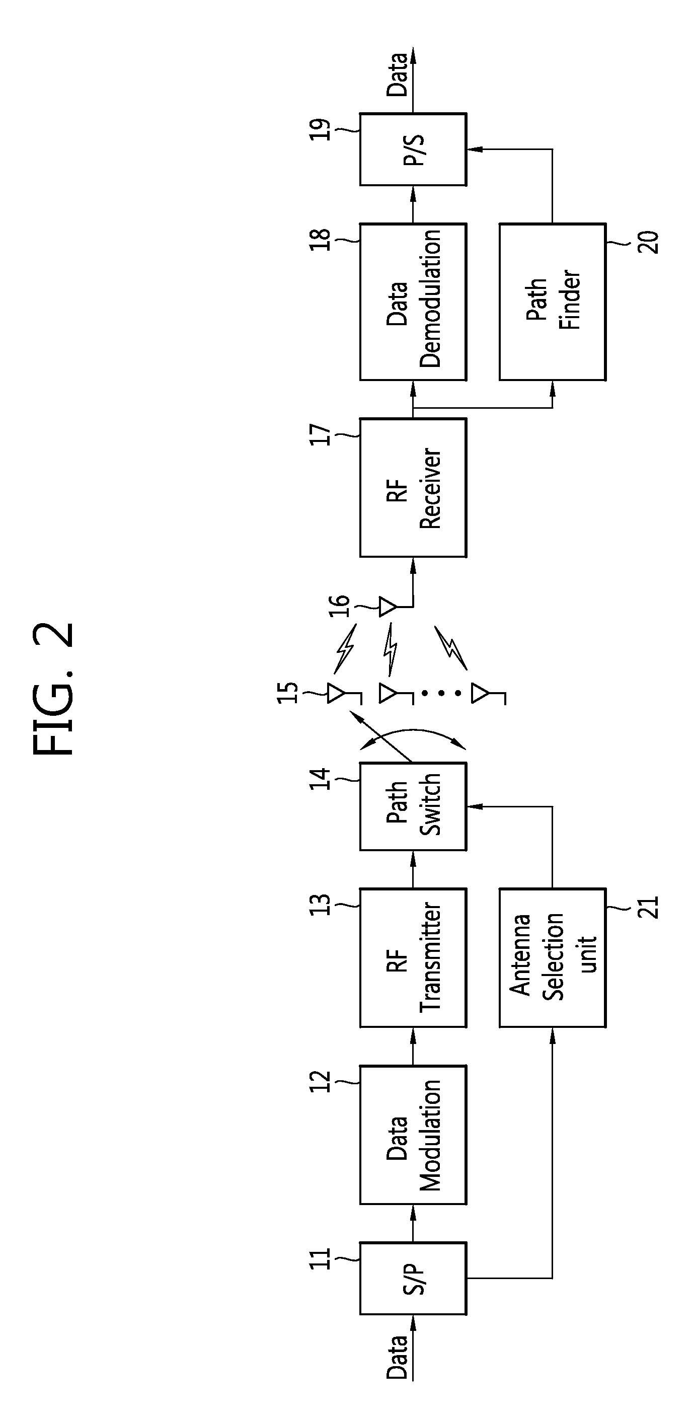
Further, in a systematic aspect, since a plurality of Radio Frequency (RF) transceivers and a plurality of antennas are required, power consumption is increased and an installation space is limited.

Method used


Image

  • Wireless communication method and apparatus based on channel function
  • Wireless communication method and apparatus based on channel function
  • Wireless communication method and apparatus based on channel function

Examples


Embodiment Construction

[0027]Exemplary embodiments of the present invention are described with reference to the accompanying drawings in detail. The same reference numbers are used throughout the drawings to refer to the same or like parts. Detailed descriptions of well-known functions and structures incorporated herein may be omitted to avoid obscuring the subject matter of the present invention.

[0028]A wireless communication system may use a frequency efficiency improving technology of transmitting data at a high rate. The frequency efficiency improving technology includes a technology of increasing a modulation level of communication or an MIMO technology of using a multiple antenna. The technology of increasing a modulation level of communication is developed together with development of a hardware design technology, and is currently developed to support 1024 Quadrature Amplitude Modulation (QAM). However, since such a technology requires a high Signal to Noise Ratio (SNR), a transmission distance is ...


PUM


Abstract

Disclosed are a wireless communication method of improving frequency efficiency based on a channel function in a wireless communication system and an apparatus thereof. The wireless communication system using a digital modulation scheme, includes: a transmitting apparatus which modulates a data signal to generate a modulation symbol, generates a channel symbol function corresponding to the modulation symbol, combines the modulation symbol with the channel symbol function to generate a transmission symbol to transmit the generated transmission symbol through a transmission antenna; and a receiving apparatus which receives the transmission symbol through a reception antenna, estimates a channel symbol function included in the transmission symbol, and extracts the data signal based on the modulation symbol included in the transmission symbol.

Description

[0001]Priority to Korean patent application number 10-2013-0146040 filed on Nov. 28, 2013 and 10-2014-0134819 filed on Oct. 7, 2014, the entire disclosure of which is incorporated by reference herein, is claimed.BACKGROUND OF THE INVENTION[0002]1. Field of the Invention[0003]The present invention relates to wireless communication, and more particularly, to a wireless communication method of improving frequency efficiency based on a channel function in a wireless communication system and an apparatus thereof.[0004]2. Related Art[0005]A technology of increasing frequency efficiency to transmit data at a high rate basically includes a technology of increasing a modulation level of communication and an MIMO technology of using a multiple antenna. The technology of increasing a modulation level of communication supports 1024 Quadrature Amplitude Modulation (QAM) together with development of a hardware design technology. However, since such a technology requires a high Signal to Noise Rat...

Claims


Application Information

Patent Timeline
Patent Type & Authority Patents(United States)
IPC IPC(8): H04L27/04H04L27/26H04L25/02
CPCH04L27/2627H04L25/0204H04L27/2649H04L27/0008H04L27/3405H04L1/06H04B7/0413H04B7/0604H04L1/0002H04L5/0023H04L27/34H04L1/0011
Inventor KIM, KWANG SEONKANG, MIN SOOKIM, BONG SUBYUN, WOO JINLIM, JONG SOOSONG, MYUNG SUNCHOI, JAE ICK
Owner ELECTRONICS & TELECOMM RES INST
Learn More