Eureka AIR delivers breakthrough ideas for toughest innovation challenges, trusted by R&D personnel around the world.

Organic light emitting device and fabricating method thereof

Active Publication Date: 2015-08-18
AU OPTRONICS CORP
View PDF6 Cites 15 Cited by
  • Summary
  • Abstract
  • Description
  • Claims
  • Application Information

AI Technical Summary

Benefits of technology

This patent describes a method of making an organic light emitting device using ink-jet printing. The method allows for the fabrication of different color patterns in specific areas of the device, resulting in optimized light emitting efficiency. This method is simpler than other methods and the resulting device has higher efficiency and a simpler structure.

Problems solved by technology

However, the technology suffers from being difficult to obtain a broader color gamut and being difficult to align a mask.
Although the technology does not require a mask for precise alignment, it suffers from a relatively less preferable color performance, higher power consumption, and being unable to respectively adjust preferred thicknesses of the red, blue, and green pixels.

Method used


Image

  • Organic light emitting device and fabricating method thereof
  • Organic light emitting device and fabricating method thereof
  • Organic light emitting device and fabricating method thereof

Examples


Embodiment Construction

[0038]Reference will now be made in detail to the present preferred embodiments of the invention, examples of which are illustrated in the accompanying drawings. Wherever possible, the same reference numbers are used in the drawings and the description to refer to the same or like parts.

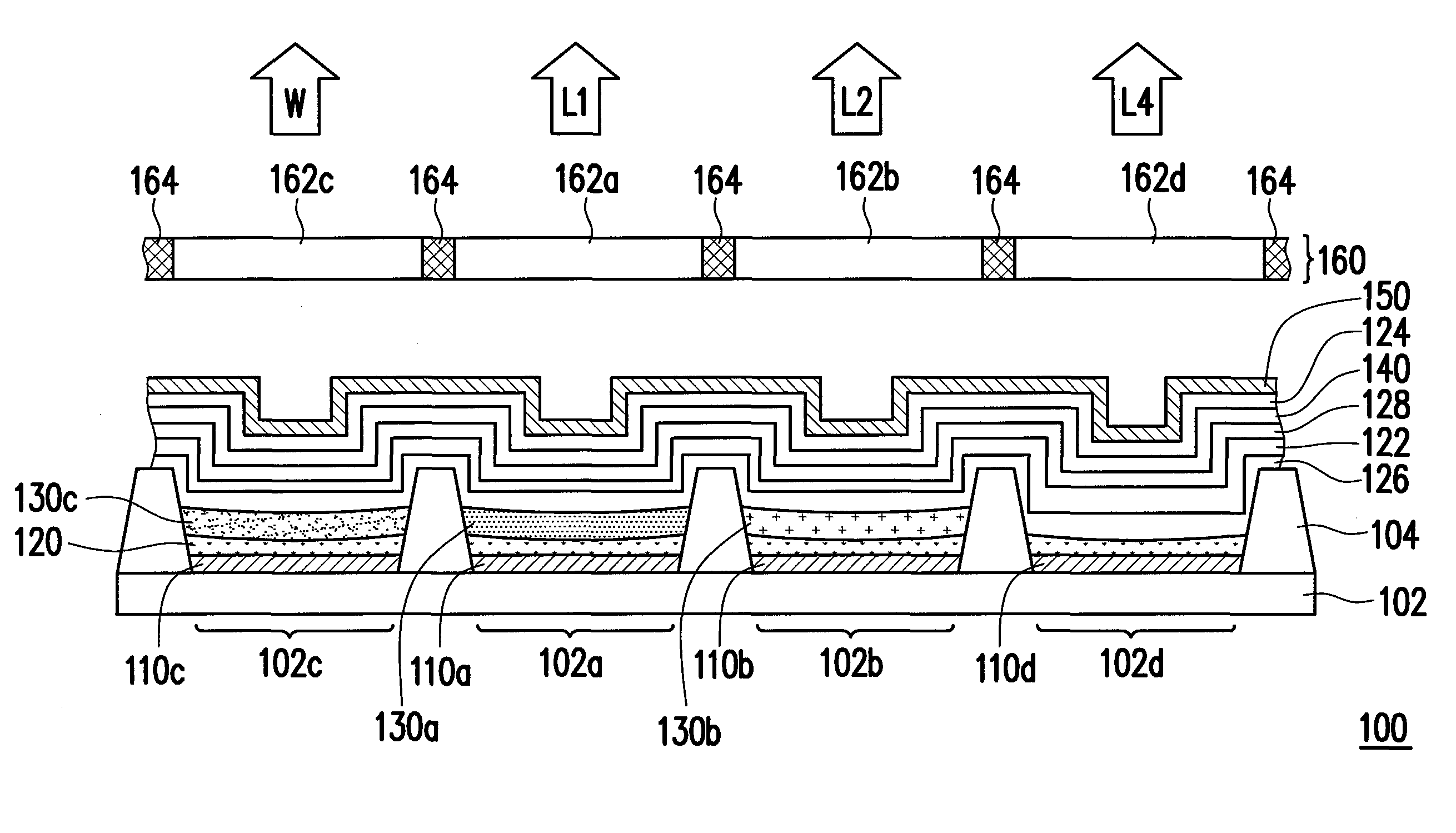
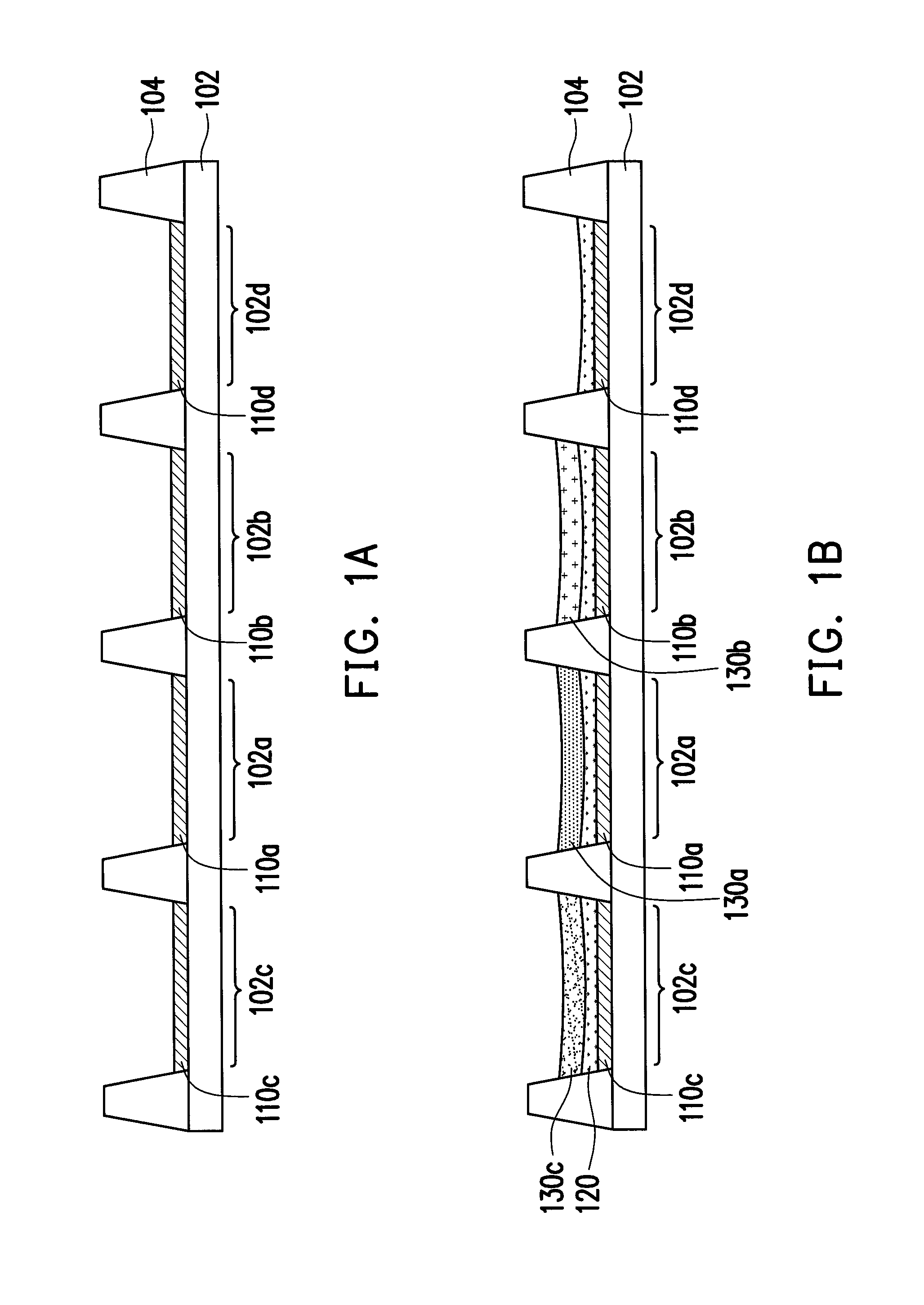
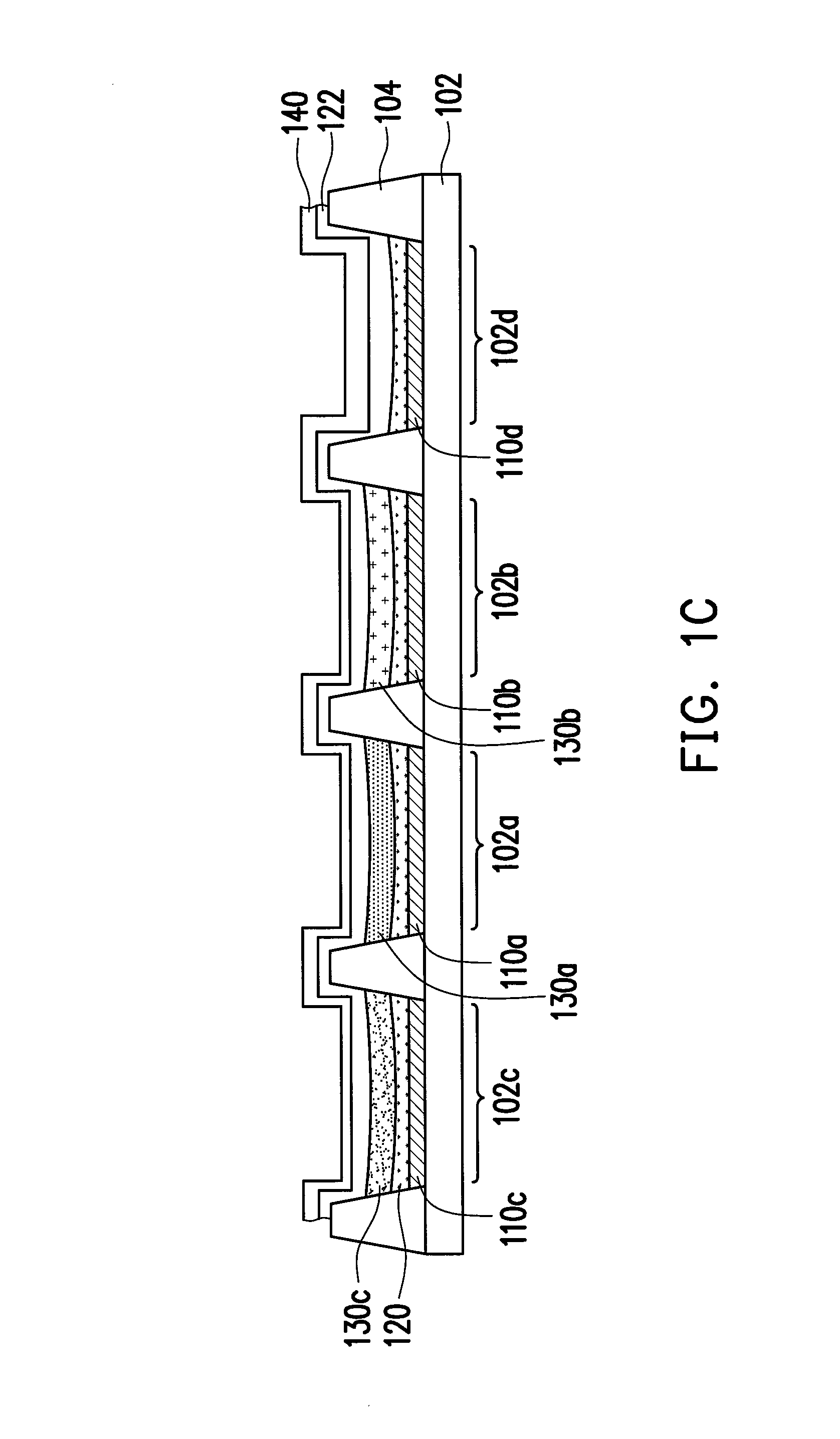
[0039]FIGS. 1A to 1E are cross-sectional views illustrating a fabricating method of an organic light emitting device according to an embodiment of the invention. Referring to FIG. 1A, a substrate 102 is firstly provided. The substrate 102 has a first pixel region 102a, a second pixel region 102b, a third pixel region 102c, and a fourth pixel region 102d. In this embodiment, the substrate 102 is disposed with an isolation structure 104, for example, to define the first pixel region 102a, the second pixel region 102b, the third pixel region 102c, and the fourth pixel region 102d that are separated from each other and arranged in the same column. Namely, as shown in FIG. 1A, the first pixel region 102a,...


PUM


Abstract

A fabricating method of an organic light emitting device is provided. First to fourth lower pixel electrodes are respectively formed in first to fourth pixel regions of a substrate. By ink-jet printing processes, an interlayer is formed on the first to fourth lower pixel electrodes, and first to third color patterns are respectively formed on the interlayer in the first to third pixel regions. A fourth color layer is formed to cover the first to third color patterns and the interlayer in the fourth pixel region. Colors of the first to third color patterns and the fourth color layer are different. An upper pixel electrode is formed on the fourth color layer. A color filter arranging over the upper pixel electrode filters out a first color light, a second color light, light of third and fourth colors, and the fourth color light corresponding to the first to fourth pixel regions.

Description

CROSS-REFERENCE TO RELATED APPLICATION[0001]This application claims the priority benefit of Taiwan application serial no. 103105530, filed on Feb. 19, 2014. The entirety of the above-mentioned patent application is hereby incorporated by reference herein and made a part of this specification.BACKGROUND OF THE INVENTION[0002]1. Field of the Invention[0003]The invention relates to a light emitting device and a fabricating method thereof, and particularly relates to an organic light emitting device and a fabricating method thereof.[0004]2. Description of Related Art[0005]Due to the advantages like self-luminescence, no viewing-angle dependence, low power consumption, simple fabrication, low costs, low working temperature, high response speed, and full-color display, organic light emitting devices (OLED) have a great potential of application and are likely to become the mainstream of the illuminating light source of flat display panels in the next generation.[0006]The full color technol...

Claims


Application Information

Patent Timeline
IPC IPC(8): H01L27/32H01L51/56
CPCH01L27/322H01L51/56H01L27/3213H10K59/38H10K59/122H10K71/10H10K71/13H10K59/351H10K71/00
Inventor CHEN, CHIH-LEIHUANG, SHENG-YANG
Owner AU OPTRONICS CORP
Why Eureka
Eureka Blog
Learn More