Apparatus and method for nasal rinsing

a technology of nasal passages and apparatus, which is applied in the field of nasal passages rinsing devices and methods, can solve the problems of sinusitis, additional symptoms, and disruption of normal sinus mucus draining,

Inactive Publication Date: 2015-08-25
JEPPSON NATHAN BLAKE
View PDF14 Cites 3 Cited by
  • Summary
  • Abstract
  • Description
  • Claims
  • Application Information

AI Technical Summary

Benefits of technology

[0011]Accordingly, the present invention provides an improved apparatus for nasal rinsing. The apparatus is configured for dispensing a solution for nasal rinsing and comprises a container having a bottom for resting on a surface and a top defining an opening. The container contains a saline solution for rinsing a nasal passage. A pump having a pump housing is disposed within the container and is coupled to the opening of the container. A pump handle is coupled to a pump shaft that is coupled to the pump housing. The pump handle is coupled to a plunger disposed within the pump housing. An elongate flexible tube is coupled at a first end to the pump handle and a nozzle configured for mating with a nostril of a user is coupled to a second end of the flexible tubing. Pumping the handle causes the saline solution to flow through the nozzle under controlled pressure into a nasal passage of a user.
[0012]In one embodiment, a first one-way valve is disposed within the housing proximate a distal end thereof for preventing flow of solution from the pump housing into the container when the pump handle is depressed. The first one-way valve comprises a first ball valve comprising a ball, a ball seat and a ball retaining structure with the ball residing between the ball seat and the ball retaining structure and movable between an open position and a closed position.
[0013]A second one-way valve is in fluid communication with the pump shaft for preventing flow of solution from the elongate flexible tubing into the pump housing when the pump shaft is extended from the pump housing. The second one-way valve comprises a second ball valve comprising a ball, a ball seat and a ball retaining structure with the ball residing between the ball seat and the ball retaining structure and movable between an open position and a closed position.

Problems solved by technology

When this occurs, normal draining of mucus within the sinuses is disrupted, and sinusitis may occur.
Allergic rhinitis may cause additional symptoms, such as sneezing and nasal itching, coughing, headache, fatigue, malaise and cognitive impairment.
The allergens may also affect the eyes, causing watery, reddened or itchy eyes and puffiness around the eyes.
This pain is typically localized to the involved sinus and may worsen when the affected person bends over or when lying down.
Often a localized headache or toothache is present.
Infection of the eye socket is possible, which may result in the loss of sight and is accompanied by fever and severe illness.
The devices illustrated in FIG. 1 has several limitations, however, including a limitation of the amount of saline solution that can be forced from the container with each squeeze of the container.
Moreover, because the device requires a squeezing of the sidewalls to expel the saline solution, it is difficult to control the pressure and thus the flow rate of solution being expelled from the device in order to provide a steady flow of solution into a nasal cavity.
Moreover, the device necessarily provides saline solution in quick bursts and therefore does not provide continuous flow of solution over any extended period of time to provide continuous flushing or rinsing of the nasal passage.
Furthermore, the size of the container to be hand held necessarily limits the amount of saline solution that can be provided in each container and therefore often requires multiple preparations to be made for each rinsing operation.
Because of these limitations, it is often the case that during use a significant amount of saline solution is wasted.
Moreover, the configuration of the device can result in contaminated material being drawn into the container during use.

Method used


Image

  • Apparatus and method for nasal rinsing
  • Apparatus and method for nasal rinsing
  • Apparatus and method for nasal rinsing

Examples


Embodiment Construction

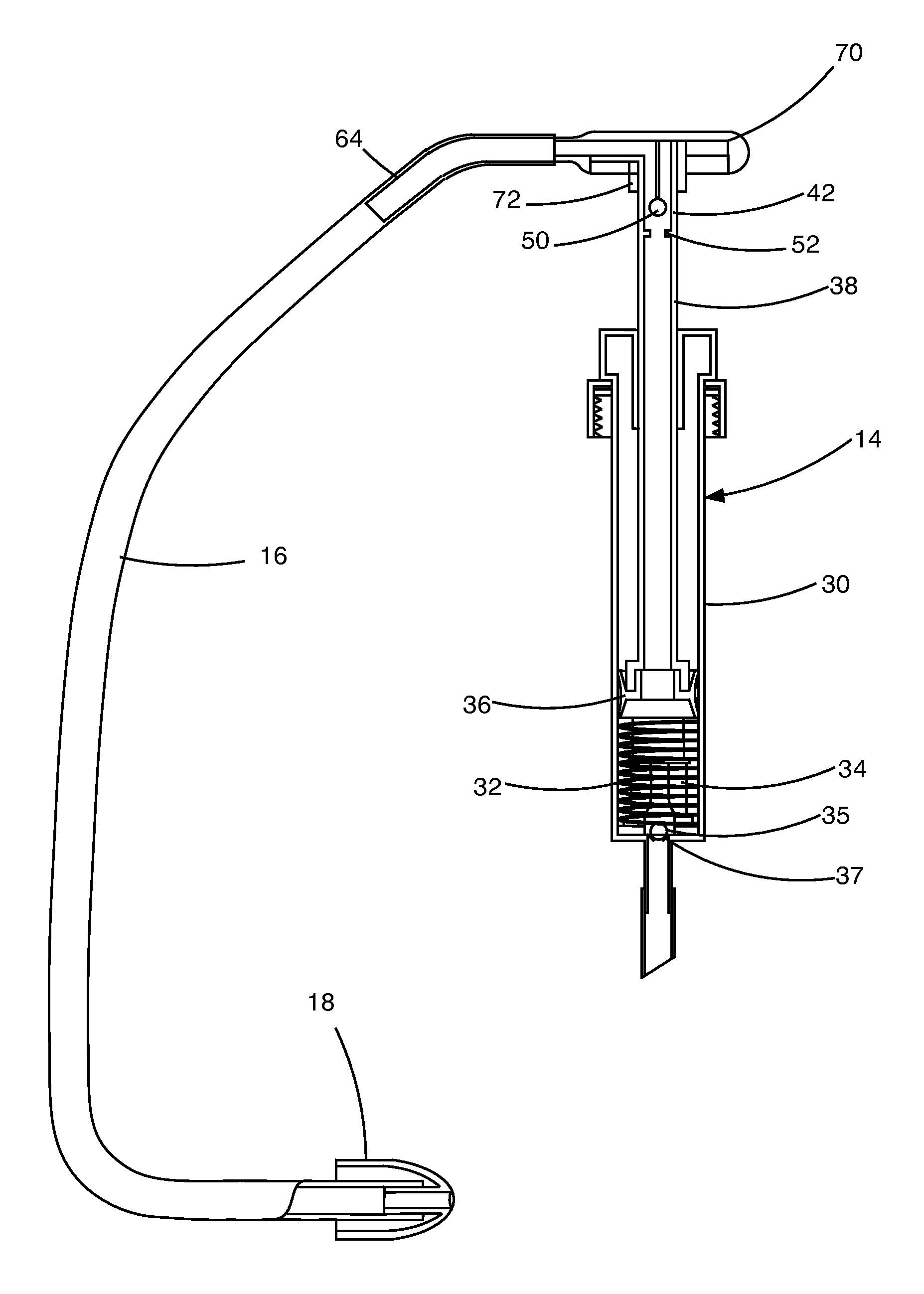
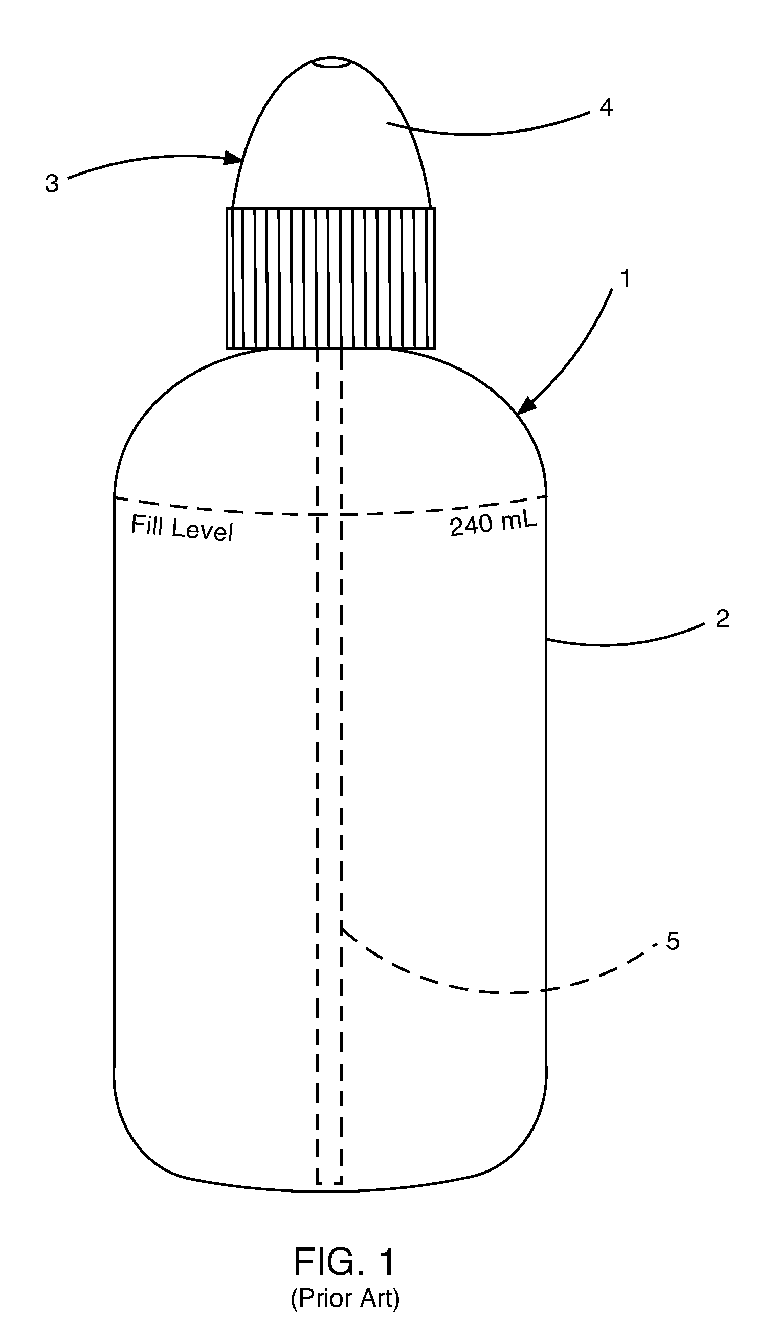
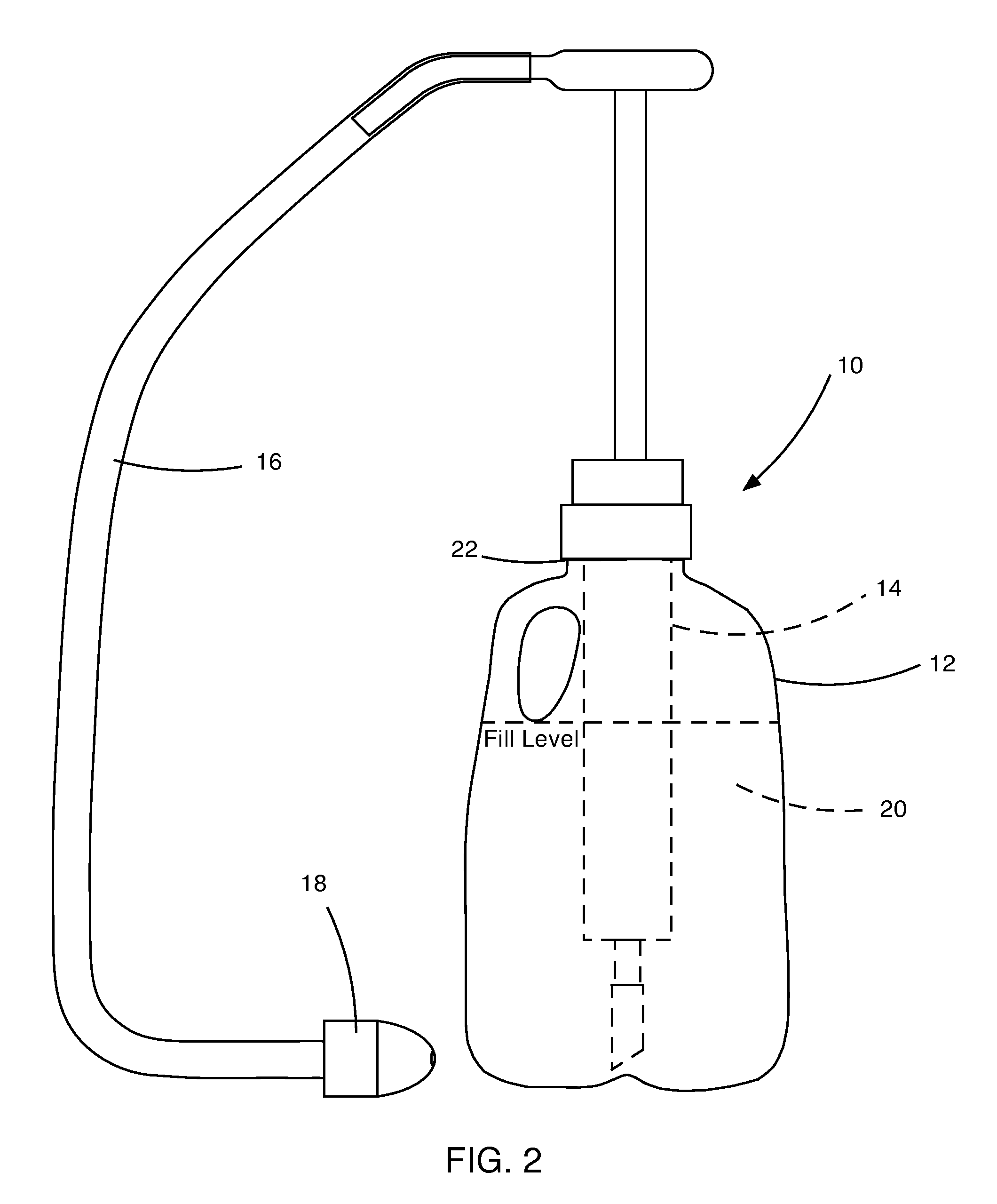
[0040]The invention and accompanying drawings will now be discussed in reference to the numerals provided therein so as to enable one skilled in the art to practice the present invention. The drawings and descriptions are exemplary of various aspects of the invention and are not intended to narrow the scope of the appended claims. Unless specifically noted, it is intended that the words and phrases in the specification and the claims be given their plain, ordinary, and accustomed meaning to those of ordinary skill in the applicable arts. It is noted that the inventor can be his own lexicographer. The inventor expressly elects, as her own lexicographer, to use only the plain and ordinary meaning of terms in the specification and claims unless they clearly state otherwise and then further, expressly set forth the “special” definition of that term and explain how it differs from the plain and ordinary meaning. Absent such clear statements of intent to apply a “special” definition, it i...


PUM


Abstract

An apparatus and method for dispensing a saline solution for nasal rinsing includes using a container having a bottom for resting on a surface and a top defining an opening. A pump having a pump housing is disposed within the container and is coupled to the opening of the container. A pump handle is coupled to a pump shaft, which is in turn coupled to the pump housing. The pump handle is coupled to a plunger disposed within the pump housing. An elongate flexible tube is coupled at a first end to the pump handle. A nozzle configured for mating with a nostril of a user is coupled to a second end of the flexible tubing. Pumping the handle causes the saline solution to flow through the nozzle under controlled pressure into a nasal passage of a user.

Description

BACKGROUND[0001]1. Field of the Invention[0002]This invention relates generally to devices and methods for rinsing nasal passages and more specifically to devices and methods for providing a pressurized flow of a saline solution into and through a nasal passage.[0003]2. State of the Prior Art[0004]The paranasal sinuses are a group of four paired air-filled spaces that surround the nasal cavity and are located above and between the eyes and behind the ethmoid sinuses. The maxillary, frontal, ethmoid and sphenoid sinuses are named for the facial bones in which they are located. The maxillary sinuses, also called the maxillary antrechea and the largest of the paranasal sinuses, are located under the eyes in the maxillary bones of the face. The frontal sinuses are located superior to the eyes in the frontal bone, which forms the hard part of the forehead. The ethmoid sinuses are formed from several discrete air cells within the ethmoid bone between the nose and eyes. The sphenoid sinuse...

Claims


Application Information

Patent Timeline
Patent Type & Authority Patents(United States)
IPC IPC(8): A61M3/02
CPCA61M3/0262A61M3/0279A61M2210/0618A61M3/0216A61M3/0208
Inventor JEPPSON, NATHAN BLAKE
Owner JEPPSON NATHAN BLAKE
Why Eureka
Try Eureka