Tattooing device

a tattooing device and tattooing technology, applied in the field of tattooing devices, can solve the problems of difficult tattooing by practitioners and severe vibration of tattooing apparatus, and achieve the effect of reducing power consumption, minimizing vibration and noise, and easy adjustment of the exposed length of the tattooing apparatus

Active Publication Date: 2015-08-25
BOMTECH ELECTRONICS
View PDF8 Cites 10 Cited by
  • Summary
  • Abstract
  • Description
  • Claims
  • Application Information

AI Technical Summary

Benefits of technology

[0011]Exemplary embodiment of the present invention addresses at least the above problems and / or disadvantages and provide at least the advantages described below. Accordingly, an aspect of the present invention is to provide a tattooing apparatus, which includes a cam link for offsetting a rotational inertia generated between a cam member and a connecting rod and which can reduce vibrations and noises by minimizing a friction force generated between the cam member and the cam link.
[0012]Another aspect of the present invention is to provide a tattooing apparatus, which can adjust an exposed length of a tattoo needle.
[0013]Further another aspect of the present invention is to provide a tattooing apparatus, which can block vibrations generated by parts operated for driving a tattoo needle to reciprocate in a straight line therein from being transmitted to a casing.

Problems solved by technology

However, since the conventional tattooing apparatus 1 as described above includes the separate rotation bar 5 for reciprocating the straight moving bar 7 in the straight line, the rotation of the rotation bar 5 synchronizes with the linear movement of the straight moving bar 7, thereby causing the tattooing apparatus to generate severe vibrations, which in turn make the practitioner difficult to exquisitely represent the tattoo.
Moreover, there was a problem in that the vibrations exert a load to the driving motor 3 to lower a driving output of the driving motor 2 and cause noises.
Also, there was a problem in that since the conventional tattooing apparatus 1 cannot adjust an exposed length of the tattoo needle 9, the practitioner has to possess each model of tattooing apparatus that a length where the tattoo needle 9 is exposed is different to perform the tattoo procedures.

Method used


Image

  • Tattooing device
  • Tattooing device
  • Tattooing device

Examples


Embodiment Construction

[0055]Hereinafter, a configuration of an tattooing apparatus according to exemplary embodiments of the present invention will now be described in greater detail with reference to the accompanying drawings.

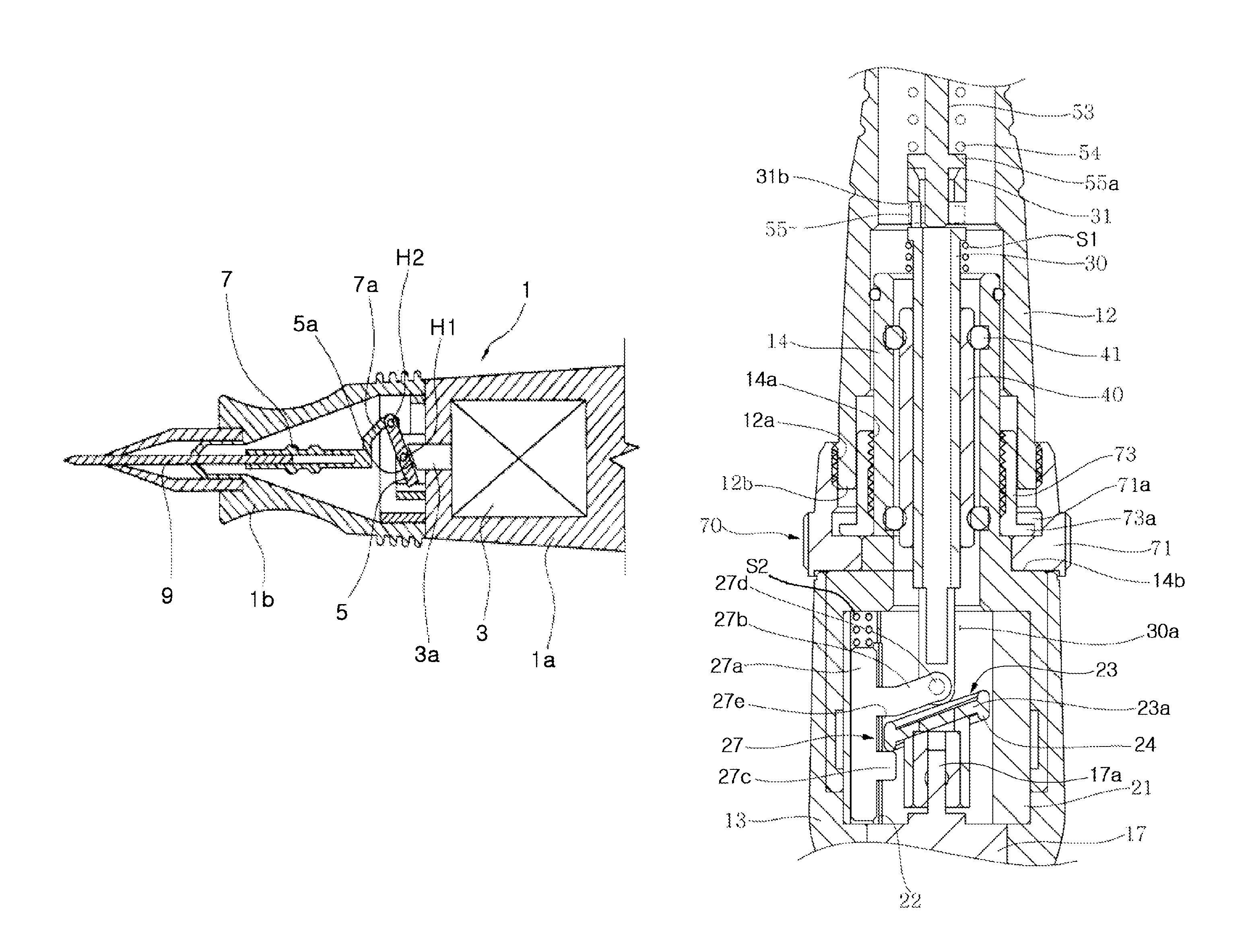
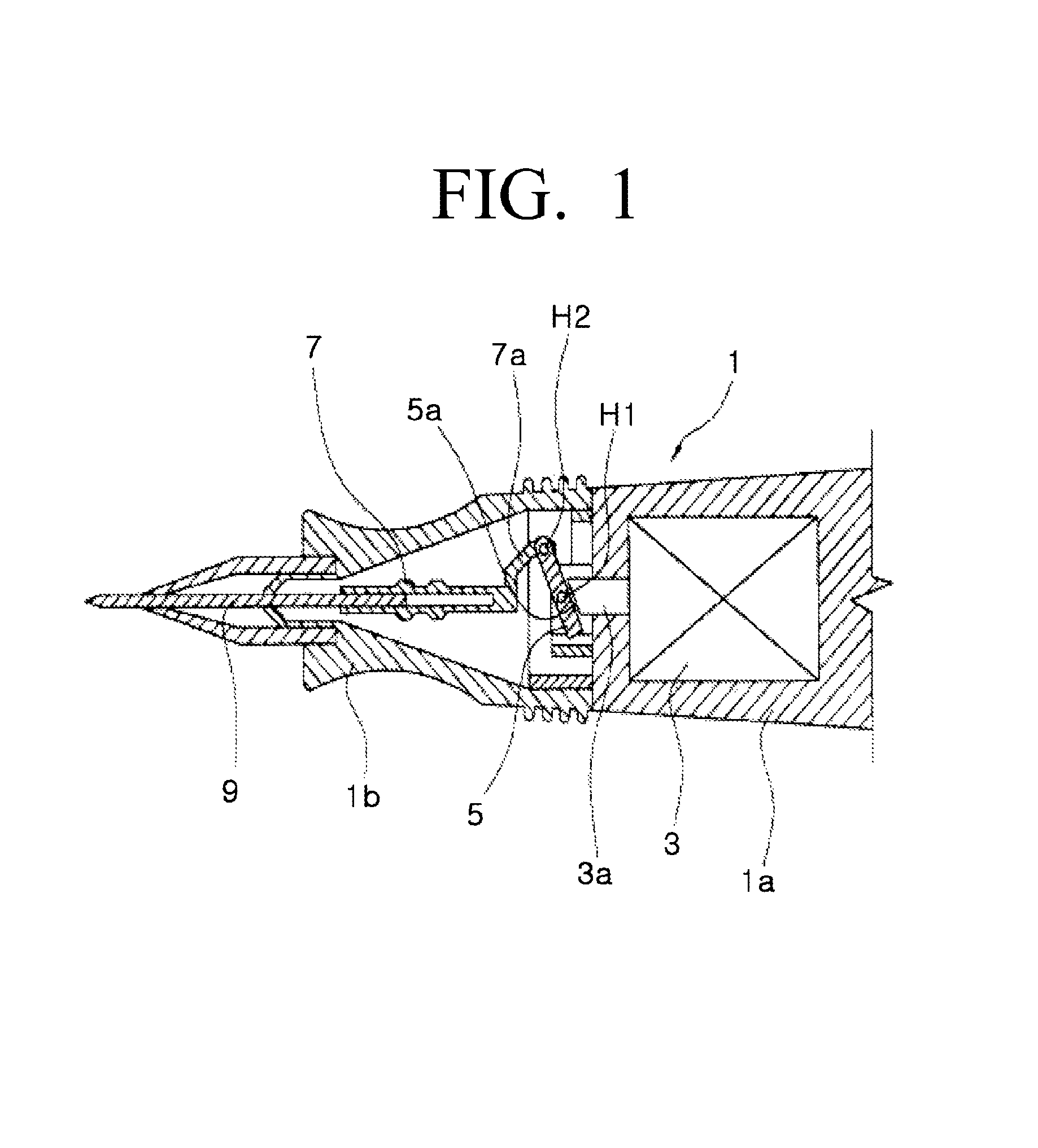
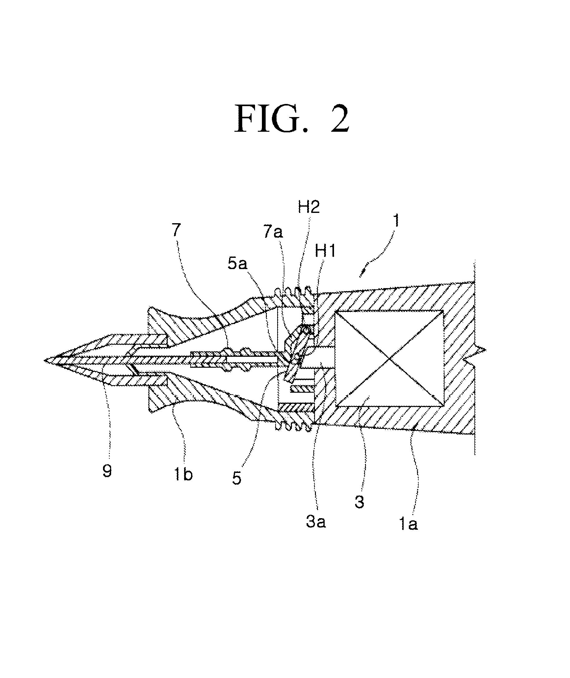
[0056]In the accompanying drawings, FIG. 3 is a perspective view showing a tattooing apparatus according to an exemplary embodiment of the present invention, FIG. 4 is a cross-sectional view taken along line A-A shown in FIG. 3, FIG. 5 is a cross-sectional view taken along line B-B shown in FIG. 4, FIG. 6 is an exploded perspective view showing a joint of the tattooing apparatus according to the exemplary embodiment of the present invention in a state before it is assembled, FIG. 7 is an enlarged view showing main parts of FIG. 4, FIG. 8 is an enlarged view showing main parts of FIG. 5, and FIG. 9 is an exploded perspective view showing according to the exemplary embodiment of the present invention.

[0057]As shown in FIG. 3, the tattooing apparatus according to the exemplary embodim...


PUM


Abstract

A tattooing apparatus includes a tattoo needle; and upward and downward moving means to transmit a rotating force of a driving motor to the tattoo needle. The upward and downward moving means consists of a cam structure to convert a rotary movement by the rotating force of a driving motor into a linear movement, and includes a bearing member for rolling contact to reduce vibrations and noises.

Description

BACKGROUND OF THE INVENTION[0001]1. Field of the Invention[0002]The present invention relates to a tattooing apparatus, and more particularly, to a tattooing apparatus, which repeatedly inserts and takes out a tattoo needle, which is driven to repeatedly travel back and forth by a driving of motor, into and from a skin thus to penetrate a pigment for tattoo into the skin.[0003]2. Description of the Related Art[0004]In general, a tattooing apparatus is an apparatus, which represents a pattern or picture, such as signs, letters, and figures, on a skin of human by using a pigment for tattoo and a tattoo needle.[0005]For convenience of tattoo procedures, a conventional tattooing apparatus is configured, so that the tattoo needle automatically travels back and forth and the pigment for tattoo rides the tattoo needle down while it travels back and forth. Here, since the tattoo needle moves while sticking at a given depth on the skin, a tattoo of given shape is represented on the skin as a...

Claims


Application Information

Patent Timeline
Patent Type & Authority Patents(United States)
IPC IPC(8): B43K5/00A61M37/00A61M5/46
CPCA61M37/0076A61M5/46A45D44/00
Inventor LEE, JONG-DAE
Owner BOMTECH ELECTRONICS
Why Eureka
Try Eureka