Dual blisks in the high-pressure compressor

a compressor and high-pressure technology, applied in the direction of arc welding apparatus, resistance welding apparatus, welding electric supply, etc., can solve the problems of material and microstructure modification unfavorable, material and microstructure modification, and inability to meet the requirements of certain joining methods

Inactive Publication Date: 2015-08-25
MTU AERO ENGINES GMBH
View PDF15 Cites 2 Cited by
  • Summary
  • Abstract
  • Description
  • Claims
  • Application Information

AI Technical Summary

Benefits of technology

[0010]The invention starts with a blisk made of a disk and a plurality of blades that are disposed on the disk, for the (high-pressure) compressor of a gas turbine, wherein the disk and / or the blades are formed from a titanium material, and specifically the titanium material Ti-6246 or Ti-6242. The titanium material Ti-6246 has a chemical composition that comprises 6 wt. % aluminum, 2 wt. % tin, 4 wt. % zirconium and 6 wt. % molybdenum with the remainder of titanium and unavoidable impurities. The titanium material Ti-6242 has a chemical composition containing 6 wt. % aluminum, 2 wt. % tin, 4 wt. % zirconium and 2 wt. % molybdenum with the remainder of titanium and unavoidable impurities. These materials have proven particularly advantageous for impellers or rotors in the high-pressure compressor of a gas turbine and especially of an aircraft engine. According to the invention, a corresponding blisk is formed for a high-pressure compressor with a disk and a plurality of blades, in which disk and blades differ in their chemical composition of the materials and / or of their microstructure. Thus, an optimal property profile of the blisk with individually adapted properties of the disk and the blades can be achieved.
[0014]The blades can or will be welded to the disk by the so-called direct high-frequency pressure welding method, in which high-frequency current is conducted through the surfaces to be joined, thus the joint surfaces of the components to be welded, i.e., the blades and disk, in the direct high-frequency pressure welding method. This can be conducted, for example, by connecting the components to be welded in series in a circuit. At the same time, the components that are to be welded are disposed at a short distance to one another, so that the current flow is limited to the surface regions, on the one hand, by the skin effect for current flow, and, on the other hand, by the proximity effect of the components disposed next to one another, so that a local heating and a local melting of the joint surfaces are produced by the high-frequency current. As soon as the joint surfaces are sufficiently heated, the components to be welded are pressed onto one another, so that bonding can take place.
[0015]This method has the advantage that it only requires a small space, since the arrangement of electrodes for introducing the current requires little space, for example, in comparison to the inductive high-frequency pressure welding method in which a corresponding induction coil is necessary for generating high-frequency induction currents. Also, in comparison to linear friction welding, which is frequently used in the production of blisks, in the case of direct high-frequency pressure welding, a much smaller space is necessary, so that the application of this method to blisks in high-pressure compressors is possible, in which a smaller structural space is available due to the plurality of blades with small dimensions.
[0016]By the direct high-frequency pressure welding method, in addition, there is the advantage that, unlike the case of linear friction welding, no relative motion of the joint surfaces to one another is necessary, which also has as a consequence corresponding advantages for the structural formation in the welding structure, since only a linear pressing movement is necessary, perpendicular to the joint surfaces. By this means, shearing forces on the structural regions next to the surface, as occur in the case of linear friction welding, are avoided, and this can be advantageously recognized correspondingly in the microstructure of the welded joint.

Problems solved by technology

The integral blading of the blisk has the disadvantage that the selection of material and the structural arrangement of the blades and the disk is limited by the manufacturing methods that are possible.
There are extensive limitations, in that the materials and their microstructure could be modified unfavorably by inappropriate joining methods or in that certain joining methods are not available for reasons of structural specifications.
Therefore, for example, welding methods may be utilized for welding blades to the disk, but these are not applicable for blisks in high-pressure compressors, even though they can be utilized for other rotors.

Method used


Image

  • Dual blisks in the high-pressure compressor
  • Dual blisks in the high-pressure compressor

Examples


Embodiment Construction

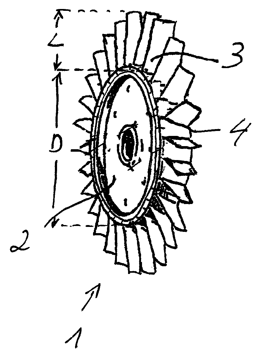
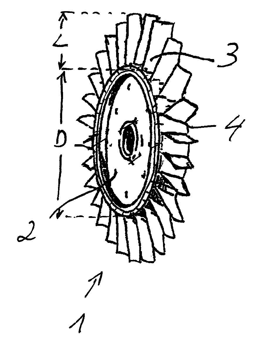
[0021]The FIGURE shows a perspective representation of a so-called blisk (bladed disk) as it is used as a rotor in a gas turbine and, in particular, in a high-pressure compressor of a gas turbine. The characterizing feature of blisk 1 is the integral design of rotor blades 3 on disk 2. The advantage of a blisk is that the joining elements between blades and disk, such as blade feet and disk channels, can be dispensed with, so that smaller edge loads result for the disk as well as a corresponding savings in weight. Of course, the selection of materials and establishing the structure of the materials in the respective components is limited by the integral design of blades and disk 2, 3. With the present invention, however, this problem can be solved, so that even in rotors or impellers in high-pressure compressors, in which there is great limitation due to the limited structural space based on the plurality of blades 3 and the small dimension of blades 3, different materials and / or ma...


PUM

PropertyMeasurementUnit
distanceaaaaaaaaaa
frequenciesaaaaaaaaaa
pressureaaaaaaaaaa

Abstract

The invention relates to a high-pressure compressor of a gas turbine having at least one blisk, specifically a disk with a plurality of blades that are disposed on the disk, wherein the blisk has at least one titanium material from the group that comprises Ti-6246 and Ti-6242, wherein the materials of the disk and the blades of the blisk differ in their chemical composition and / or their microstructure. The blades are welded to the disk, in particular, by means of a pressure welding method supported by high-frequency current, whereby the current is conducted through the joint surfaces and leads to local limited melting therein.

Description

BACKGROUND OF THE INVENTION[0001]1. Field of the Invention[0002]The invention relates to a high-pressure compressor in a gas turbine, particularly of an aircraft engine with at least one blisk made of a disk and a plurality of blades that are disposed on the disk, or a corresponding blisk that that is formed from at least one material from the group that comprises Ti-6246 and Ti-6242.[0003]2. Prior Art[0004]Compressors of gas turbines and aircraft engines, in particular, serve for compressing suctioned quantities of air that are burned in the combustion chamber along with the fuel. In today's engines, compression ratios of more than 30 to 1 are achieved in this way, wherein different compressor stages are utilized, i.e., low-pressure and high-pressure compressors. These compressors have a plurality of compressor impellors or rotors disposed one behind the other that very rapidly rotate between stationary guide blades. The compressor impellors are moved via shafts driven by the turbi...

Claims


Application Information

Patent Timeline
Patent Type & Authority Patents(United States)
IPC IPC(8): B23K11/24F01D5/14F01D5/30F01D5/34F04D29/02F04D29/32B23K11/02
CPCB23K11/02F01D5/3061F01D5/34F04D29/023F04D29/321F04D29/324B23K2201/001B23K2203/14F05C2201/90B23K2101/001B23K2103/14F05D2300/174F05D2300/608
Inventor GINDORF, ALEXANDERKLEMM, MARCUS
Owner MTU AERO ENGINES GMBH
Why Eureka
Try Eureka