Electronic drill guide

a drill guide and electronic technology, applied in the field of electronic drill guides, can solve the problems of difficulty in consistently drilling perpendicular holes using a hand-held power drill, affecting the visibility of the surface, and cumbersome mechanical jigs, and achieve the effect of convenient viewing

Active Publication Date: 2015-08-25
MAH KENNETH JACK
View PDF33 Cites 228 Cited by
  • Summary
  • Abstract
  • Description
  • Claims
  • Application Information

AI Technical Summary

Benefits of technology

[0016]In accordance with one embodiment, an electronic drill guide for a hand-held power drill comprises a three-axis accelerometer, at least two forward-facing distance sensors, and a projection display. The drill orientation relative to the target surface is mapped t...

Problems solved by technology

In practice, it is very difficult to consistently drill perpendicular holes using a hand-held power drill, particularly when the operator cannot stand directly behind the drill such as when the operator is reaching overhead.
Mechanical jigs are cumbersome and sometimes even dangerous to use.
Such jigs are typically temporarily installed on the target surface which hinders visibility of the surface.
Bubble levels work well when drilling into horizontal surfaces but it can be burdensome to view and position the small bubble between the lines.
Bubble levels do not provide a full solution when drilling into vertical target surfaces such as a wall.
When drilling a vertical surface, the bubble level can only help the drill operator align the drill perpendicular to the wall in ...

Method used


Image

  • Electronic drill guide
  • Electronic drill guide
  • Electronic drill guide

Examples


first embodiment

2, 7-9, 12A-12J

[0126]The following description is not to be taken in a limiting sense, but is made merely for the purpose of describing the general principles of the electronic drill guide. The scope of the drill guide should be determined with reference to the claims.

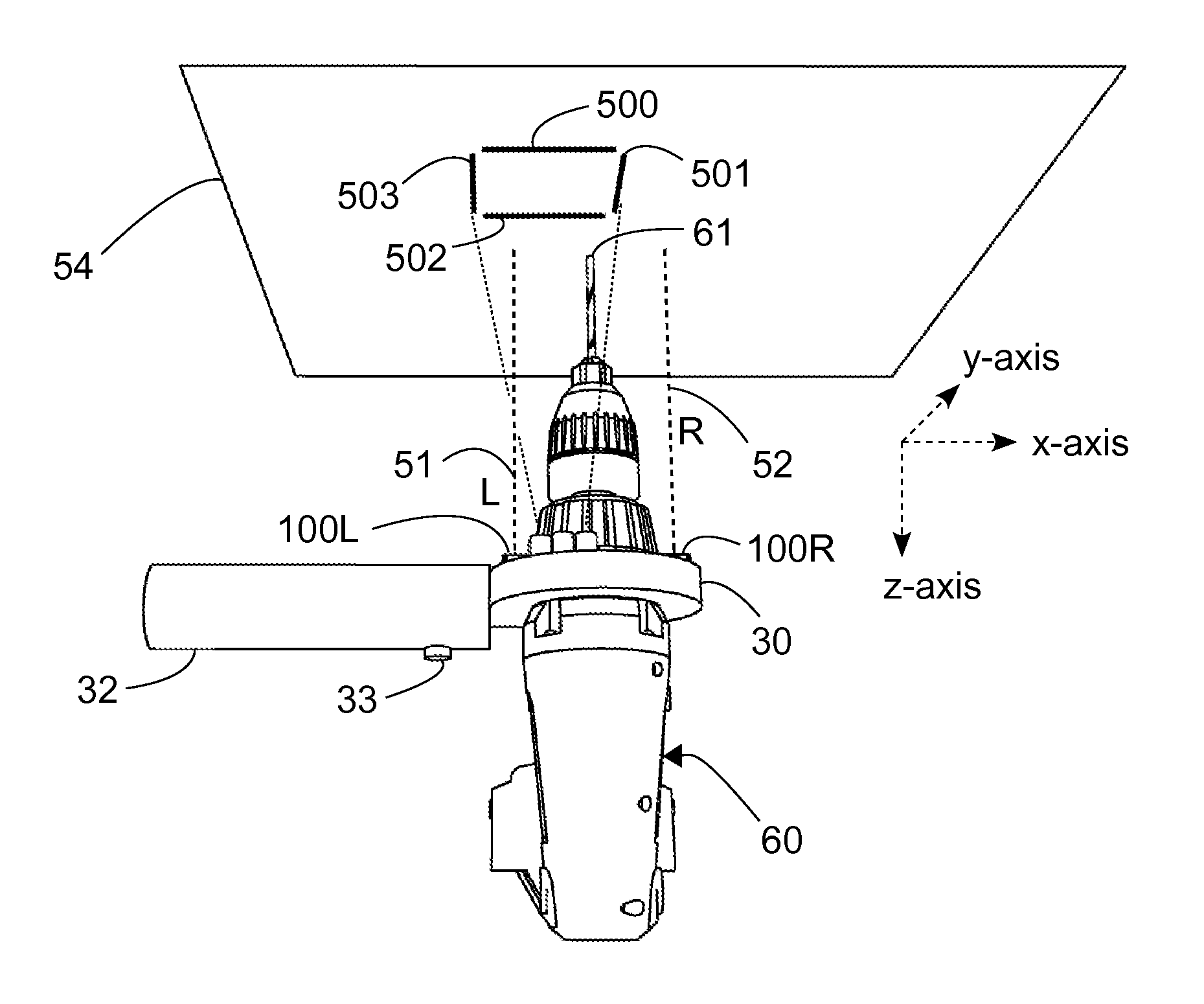
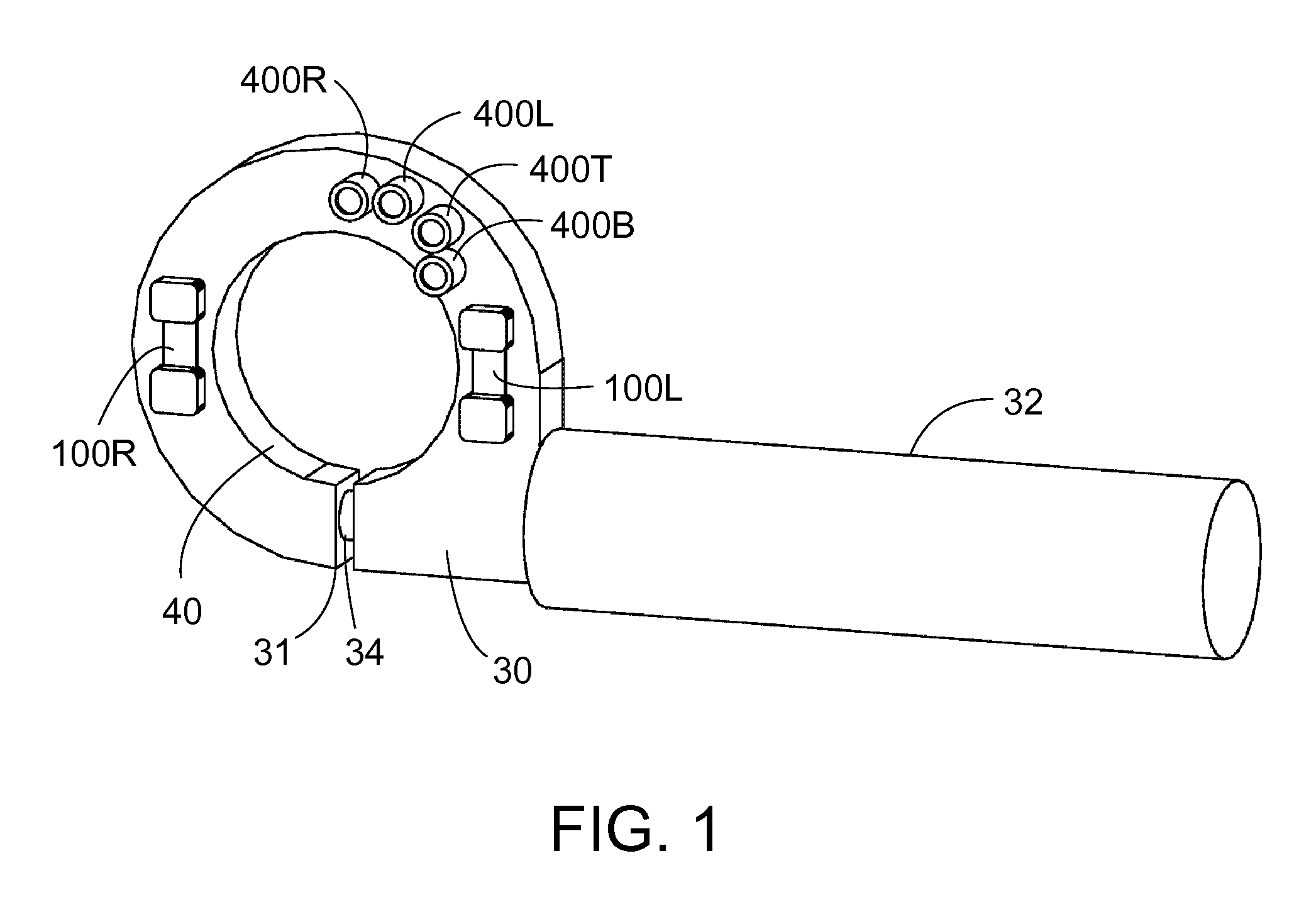
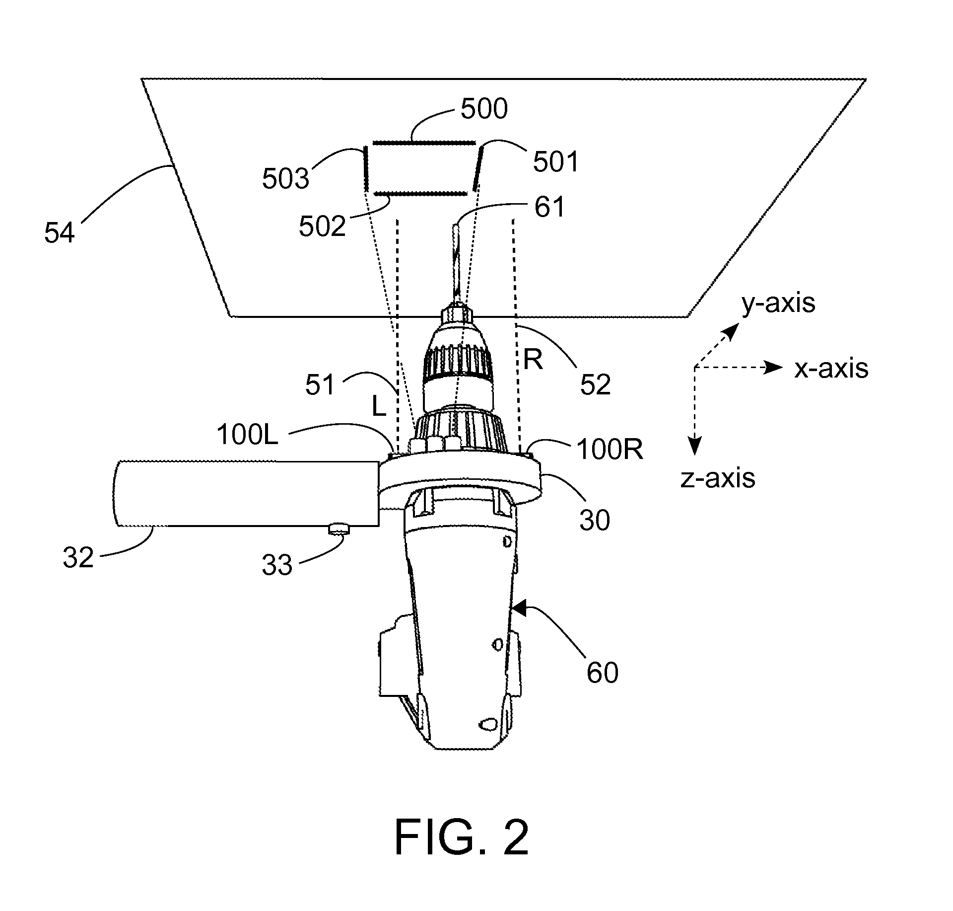
[0127]FIG. 1 shows a perspective front view of the electronic drill guide constructed in accordance with one embodiment. This embodiment is in the form of an auxiliary handle for a power drill. An enclosure 30 has an opened collar 40 which fits around the neck of a power drill. The collar 40 has a gap 31. A handle 32 is connected to a threaded bolt 34 which is threaded into the enclosure 30 such that twisting the handle 32 tightens or loosens the collar 40. Batteries (not shown) are contained within the handle 32. Referring to FIG. 2 and FIG. 4, the power drill 60 has a drill bit 61 which rotates about a working axis or drilling axis 53. The base of the drill 60 has a battery pack 65. The enclosure 30 has a front plane...


PUM


Abstract

One embodiment of an alignment apparatus for aligning an object, such as a tool or other implement, perpendicular with respect to a horizontal or a vertical target surface, comprises a three-axis accelerometer and at least two forward-facing distance sensors and a projection display comprising four addressable laser projectors. The accelerometer and distance sensor outputs are mapped to a predefined graphic symbol representing the orientation of the tool relative to the target surface, in particular when the tool is perpendicular to the target surface. The projection display projects the predefined symbol onto the target surface where it may be easily viewed by the tool operator allowing the operator to make any necessary corrections to the tool position.

Description

CROSS-REFERENCE TO RELATED APPLICATIONS[0001]This application claims the benefit of provisional patent application Ser. No. 61 / 678,868 filed 2012 Aug. 2 by the present inventor.BACKGROUNDPrior Art[0002]The following is a tabulation of some prior art that presently appears relevant:[0003]U.S. PatentsU.S. Pat. No.Kind CodeIssue DatePatentee1,234,594A1917-07-24Wilner2,822,615A1958-02-11Durst et al.3,052,036A1962-09-04Oliver4,141,151A1979-02-27Jansky4,154,001A1979-05-15Serafin4,179,231A1979-12-18Hadden4,295,279A1981-10-20Sienknecht4,393,599A1983-07-19Sterrenberg4,457,078A1984-07-03Suchy4,765,786A1988-07-23Krogh6,247,879B12001-06-19Costa6,375,395B12002-04-23Heintzeman6,499,219B12002-12-31Wightman6,587,184B22003-07-01Wursch et al.6,878,954B22005-04-12Butler et al.6,898,860B22005-05-31Wu7,154,406B12006-12-26Judge7,200,516B12007-04-03Cowley7,874,077B22011-01-25Borinato7,992,311B22011-08-09Cerwin[0004]U.S. patent application publicationsPublication Nr.Kind CodePublication DateApplicant2004 / 0...

Claims


Application Information

Patent Timeline
IPC IPC(8): A63B69/36B23Q17/24B23B49/00B23Q17/22B27G23/00G01D21/00B25H1/00A61B17/00B25C7/00G01B11/26A63B53/04
CPCB23Q17/2233B23Q17/2414B25H1/0092A63B69/3685A61B2017/00725B25C7/00G01B11/26B23Q17/24A63B53/0487B23Q17/2225
Inventor MAH, KENNETH JACK
Owner MAH KENNETH JACK
Why Eureka
Try Eureka