
Chainlink memory

a chainlink and memory technology, applied in the field of magnetic shift registers, can solve the problems of impeded commercial deployment today, prohibitively complex fabrication process, complicated control of racetrack memories,

Inactive Publication Date: 2015-08-25
IRON CITY INTEGRATED CIRCUITS
View PDF6 Cites 3 Cited by
  • Summary
  • Abstract
  • Description
  • Claims
  • Application Information

AI Technical Summary

Benefits of technology

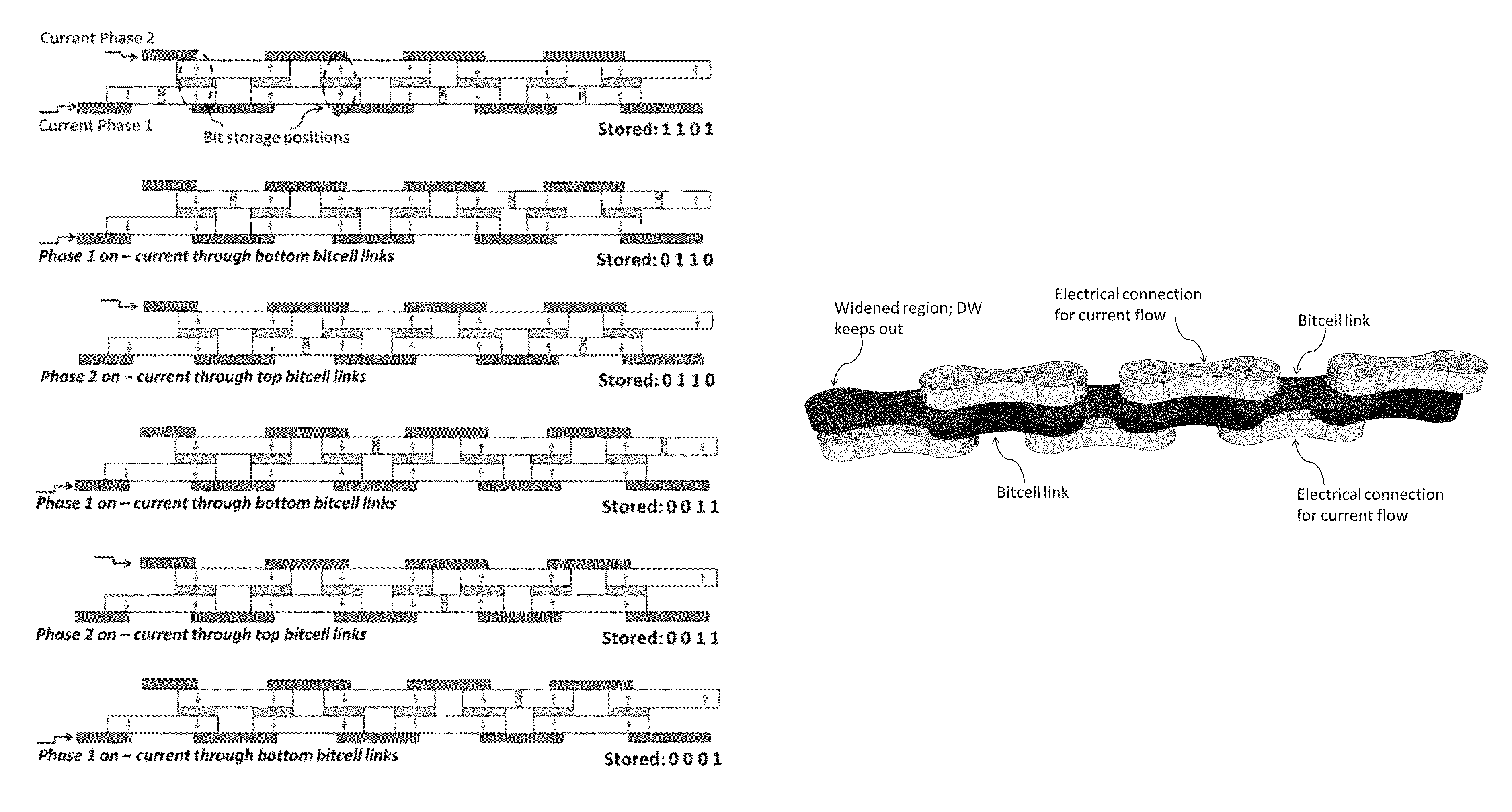
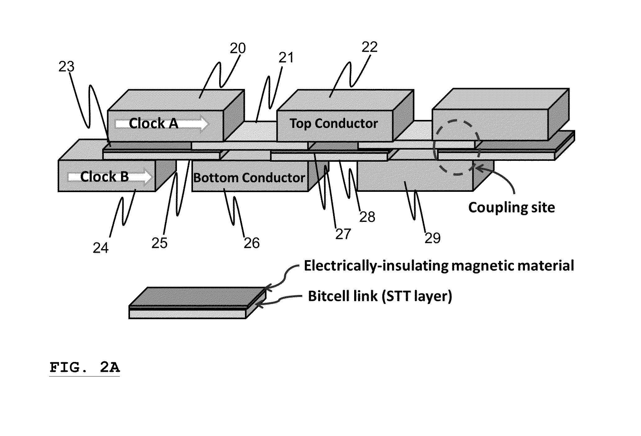
The patent describes a type of computer memory called chainlink memory, which is designed to use less power and have better performance than traditional memory. The unique feature of chainlink memory is that each bit of data is not spread out over multiple tracks, but instead is programmed in a separate region and then transferred to another region using a magnetic coupling process. This design allows for better control and prevents data loss. The patent also discusses the use of two-phase clocking to further improve the performance of the memory. Overall, the patent provides technical details and evidence that chainlink memory could become a better choice for computer memory in the future.

Problems solved by technology

3D versions of such structures have been proposed, but the fabrication process is prohibitively complex.
While racetrack memory remains a potentially interesting technology that might have commercial value in the future, there are numerous problems that impede its commercial deployment today.
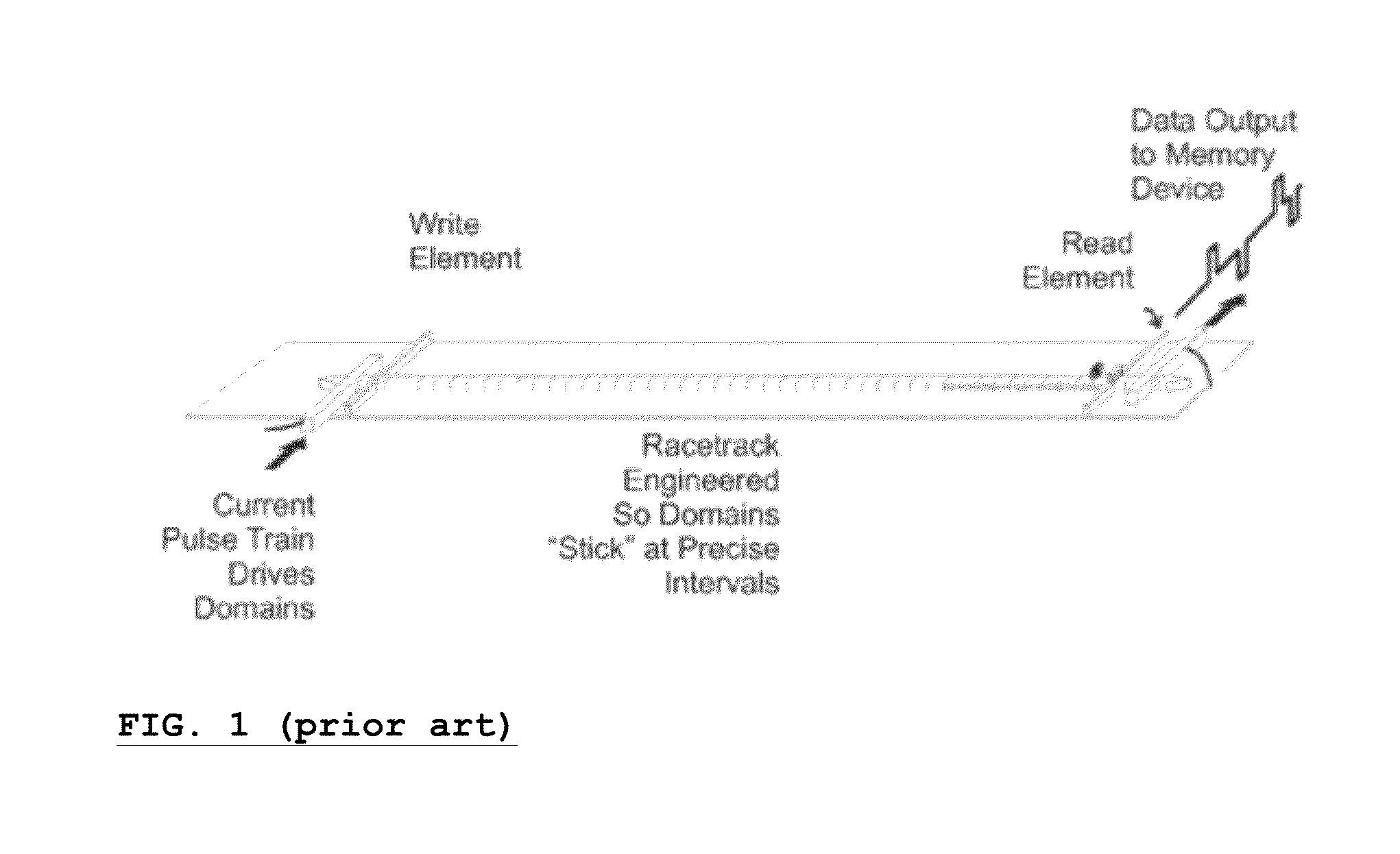
Racetrack memories are complicated to control, requiring precise timing and pulse generation to move the domain walls along the track simultaneously and at the appropriate speed, as well as having them stop in the low energy positions.
Most importantly, however, adjacent domain walls in the track—effectively the bits of data—occasionally annihilate each other during motion.
This annihilation of domain walls represents a loss of data in the memory.

Method used


Image

  • Chainlink memory
  • Chainlink memory
  • Chainlink memory

Examples


Embodiment Construction

Inventors' Lexicography

[0048]As used in this disclosure and the claims that follow, unless the context clearly demonstrates otherwise, the term “insulator” shall refer to a material or region whose principal function in the device or system is to prevent current flow across or through the material or region. In other words, the presence or possibility of some de minimis current flow across or through a material or region would not disqualify such material or region as an “insulator,” so long as the implicated current flow was not of a magnitude that would materially impede the material's or region's insulating function within the system or device. Other versions of the word (e.g., “insulate,”“insulates,” etc.) shall be similarly defined, unless the context clearly dictates otherwise.

[0049]As used in this disclosure and the claims that follow, unless the context clearly demonstrates otherwise, the term “couple” shall refer to an interaction between two or more elements with magnetiza...


PUM


Abstract

A nonvolatile alternative to DRAM or Flash is disclosed. It involves a new “magnetic shift register” that avoids the bit annihilation problem that plagues magnetic racetrack memories. Using this new “chainlink memory” approach, one avoids the annihilation problem inherent in racetrack memory by breaking up the racetrack into magnetically coupled links, where each link preferably handles one bit exclusively. Depending upon the implementation, the “bit” can be, for example, the magnetization of a link, presence or absence of a domain wall, or the polarity of a domain wall. Numerous examples and applications of this new chainlink technology are disclosed.

Description

CROSS-REFERENCE TO RELATED APPLICATION[0001]This application claims priority from U.S. provisional application Ser. No. 61 / 641,296, “Chainlink Memory,” filed May 1, 2012 by the inventors herein, which provisional application is incorporated into the present application by reference.BACKGROUND[0002]In recent years, a magnetic shift register termed “racetrack memory” has come into the spotlight as a dense memory technology. Racetrack memory operates by pushing magnetic domain walls (i.e., the “walls” that define regions of opposing magnetization in a magnetic material) along a track composed of a magnetic wire. In some prior art devices, stable domain wall positions are created by adding “notches” along a track. In racetrack memories, the domain wall shifting mechanism is believed to be spin-transfer torque (STT), where a spin-polarized input current imparts a torque on local magnetic moments, causing them to align in the direction of the electron spin. FIG. 1 (adapted from FIG. 4A of...

Claims


Application Information

Patent Timeline
Patent Type & Authority Patents(United States)
IPC IPC(8): G11C19/00G11C19/02
CPCG11C19/02G11C19/08G11C19/0808G11C19/0841G11C2213/71G11C11/161G11C11/1675
Inventor MORRIS, DANIEL H.BROMBERG, DAVID M.PILEGGI, LAWRENCE T.ZHU, JIAM-GANG JIMMY
Owner IRON CITY INTEGRATED CIRCUITS
Learn More