Supercharge Your Innovation With Domain-Expert AI Agents!

Stator, motor, and compressor

a technology of stator and motor, applied in the direction of windings, mechanical energy handling, magnetic circuit shape/form/construction, etc., can solve the problem of not being able to precisely position the stator, and achieve the effect of preventing excess varnish and precise positioning of the stator

Active Publication Date: 2015-08-25
DAIKIN IND LTD
View PDF18 Cites 4 Cited by
  • Summary
  • Abstract
  • Description
  • Claims
  • Application Information

AI Technical Summary

Benefits of technology

The present invention provides a motor design with several advantages. Firstly, a protrusion is provided on the outer surface of the motor's wall portion, which prevents excess varnish from running down to the end surface of the core during the drying process. This prevents the stator from losing balance and ensures precise positioning during installation. Secondly, excess varnish is retained in a groove formed at a specific position, further preventing it from causing issues during the drying process. Overall, this design improves the performance and reliability of the motor.

Problems solved by technology

However, in spite of the fact that the varnish has been wiped by a wiping operation conducted before the drying process, there may be a case where, for example, excess varnish runs down to and attaches to the end surface of the core in the drying process.
This case presented a problem that it is not possible to precisely position the stator in a process of installing the stator into a casing using shrink fitting or the like because, for example, the stator loses its balance and is thereby inclined obliquely.

Method used


Image

  • Stator, motor, and compressor
  • Stator, motor, and compressor
  • Stator, motor, and compressor

Examples


first embodiment

[0049](First Embodiment)

[0050]The following describes a first embodiment of a stator, a motor, and a compressor, in accordance with the present invention.

[0051]

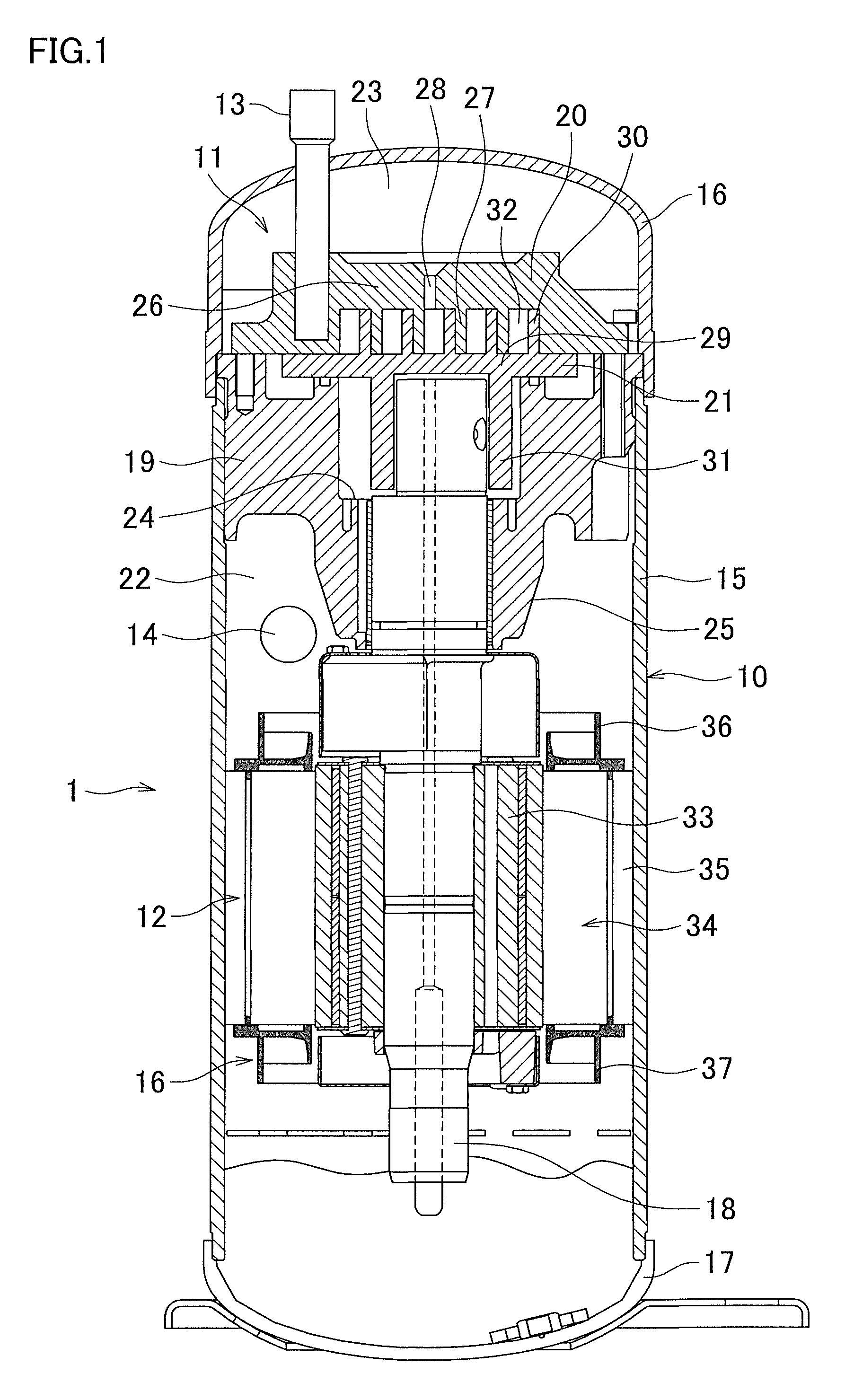
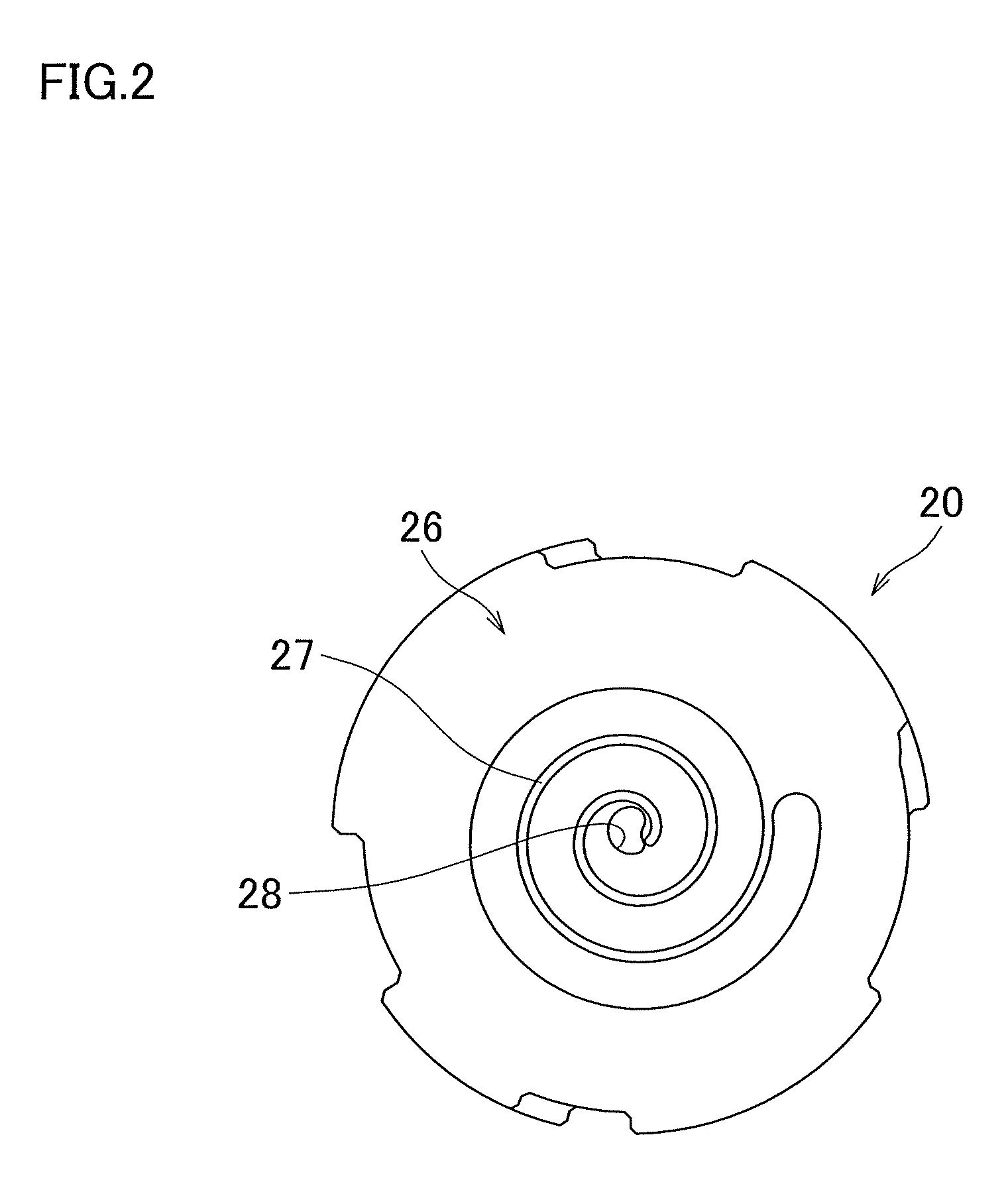
[0052]FIG. 1 is a sectional view illustrating a scroll compressor 1 (compressor) of the first embodiment of the present invention. FIG. 2 is a plan view illustrating a fixed scroll member 20 which will be described later. The scroll compressor 1 constitutes a refrigerant circuit, together with an evaporator, a condenser, an expansion valve, and the like, and functions to compress a gas refrigerant in the refrigerant circuit. The scroll compressor 1 is constituted by a generally cylindrical casing 10 of hermetic dome type, a scroll compression mechanism 11, a motor 12, an intake pipe 13, a discharge pipe 14, and the like. Hereinafter, details on these main components will be described.

[0053]

[0054]The casing 10 has a substantially cylindrical casing body 15, a bowl-like top wall portion 16 airtightly welded to an upper end port...

second embodiment

[0082](Second Embodiment)

[0083]The following describes a second embodiment of the stator, motor, and compressor of the present invention. In this embodiment, same components as those described in the first embodiment will be given the same reference numerals, and detailed description thereof will be omitted. FIG. 8 is an explanatory diagram illustrating the upright position drying process.

[0084]

[0085]As shown in FIG. 8, an insulator 136 of this embodiment differs from that of the above-described first embodiment in that, on a surface 148a of a protrusion 148 (surface on an opposite side of the protrusion 148 from a core 35) corresponding to the protrusion 48 (see FIG. 7) of the insulator 36 of the first embodiment, a groove 148b is formed at a position apart from an outer edge of the protrusion 148.

[0086]A bold arrow illustrated in an enlarged view of a portion encircled by an alternate long and short dash line (a portion in the vicinity of a coil 78) in FIG. 8 shows a flow of exces...

third embodiment

[0090](Third Embodiment)

[0091]The following describes a third embodiment of the stator, motor, and compressor of the present invention. In this embodiment, same components as those described in the first embodiment will be given the same reference numerals, and detailed description thereof will be omitted. FIG. 9 is an explanatory diagram illustrating the upright position drying process.

[0092]

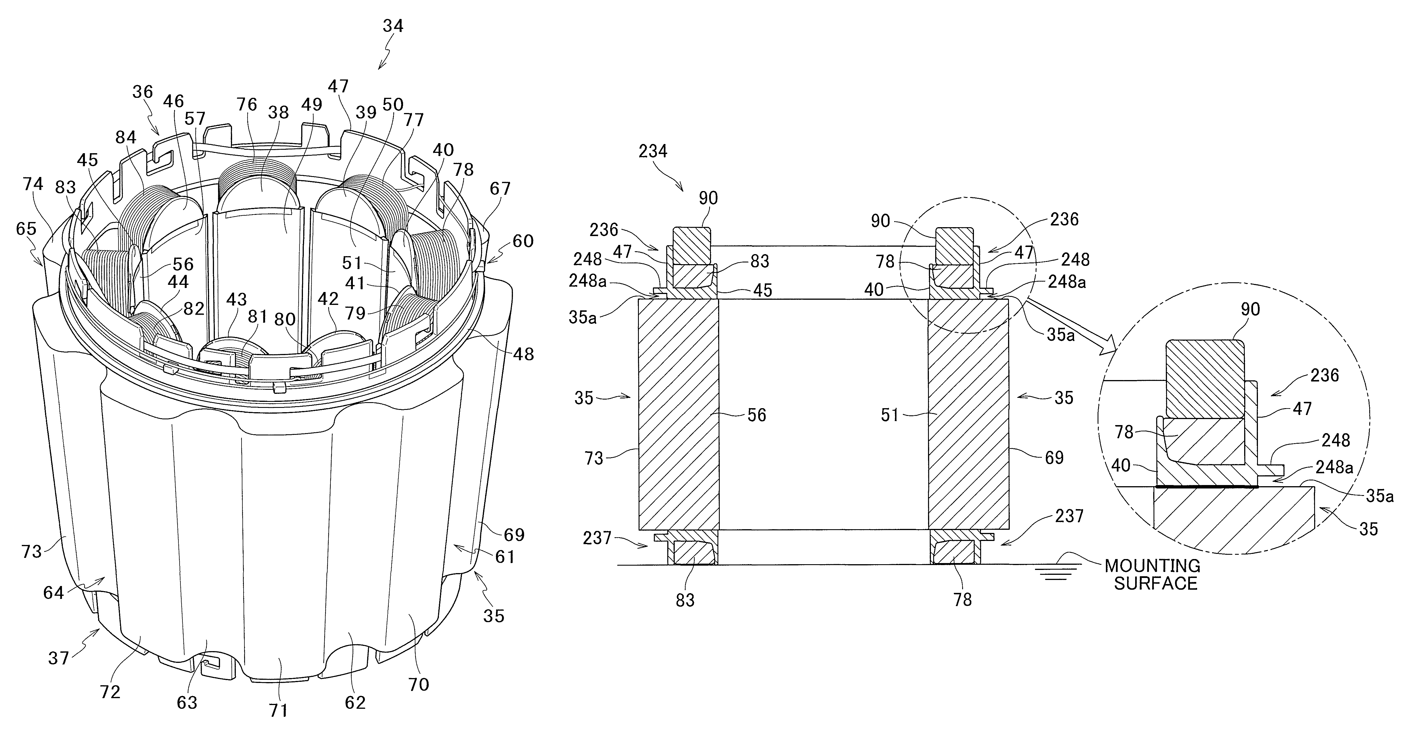
[0093]As shown in FIG. 9, an insulator 236 of this embodiment differs from that of the above-described first embodiment in that a gap 248a is created across the entire circumference of a protrusion 248, which corresponds to the protrusion 48 (see FIG. 7) of the insulator 36 of the first embodiment, and between the protrusion 248 and an end surface 35a of a core 35; and in that an insulator 237, which corresponds to the insulator 37 (see FIG. 7) of the first embodiment, is formed into a substantially same shape as the insulator 236.

[0094]As shown in an enlarged view of a portion encircled by an ...


PUM


Abstract

A stator includes a core and an insulator. The core has a plurality of annularly arranged tooth portions. The insulator is disposed on an end portion of the core, and has an annular wall portion extending in a direction departing from the core. A protrusion protrudes radially outward across an entire circumference of the wall portion, and the protrusion is provided on an outer circumferential surface of the wall portion.

Description

CROSS-REFERENCE TO RELATED APPLICATIONS[0001]This U.S. National stage application claims priority under 35 U.S.C. §119(a) to Japanese Patent Application No. 2009-022161, filed in Japan on Feb. 3, 2009, the entire contents of which are hereby incorporated herein by reference.TECHNICAL FIELD[0002]The present invention relates to a stator of a motor used in industrial equipment, office equipment, equipment for household electrical appliances, and the like, and a motor and a compressor to each of which this stator is applied.BACKGROUND ART[0003]Conventionally, as a synchronous motor incorporated in, and functioning as a part of, a motor-integrated hydraulic pump which is mounted on a motor vehicle or the like, there has been known a synchronous motor which is provided adjacent to a pump in a casing (see Japanese Unexamined Patent Publication No. 2005-287240). As described in the patent document 1, the motor is constituted as a three-phase brushless motor, and has: a stator having coils ...

Claims


Application Information

Patent Timeline
IPC IPC(8): H02K3/38H02K15/12H02K3/52H02K1/18H02K7/14
CPCH02K3/522H02K15/12H02K1/185H02K7/14H02K2203/06
Inventor TSUKAMOTO, SATOSHISHIRASAKA, HIROKIKAGAWA, YOSHINORIMURAKAMI, SEIICHI
Owner DAIKIN IND LTD
Features
  • R&D
  • Intellectual Property
  • Life Sciences
  • Materials
  • Tech Scout
  • Unparalleled Data Quality
  • Higher Quality Content
  • 60% Fewer Hallucinations
Learn More