
Method of and a device for forming a projection on a metal member and a metal part processed by the method of forming a projection

a technology of metal parts and projections, which is applied in the field of methods and devices for forming projections on metal parts and metal parts processed by the method of projections, can solve the problems of friction welding not providing a good dimensional accuracy, welding and brazing techniques, and inapplicability of pressing, etc., and achieve excellent mechanical properties, excellent mechanical properties, and excellent mechanical properties.

Inactive Publication Date: 2015-09-01
YAMANOISEIKI
View PDF54 Cites 5 Cited by
  • Summary
  • Abstract
  • Description
  • Claims
  • Application Information

AI Technical Summary

Benefits of technology

The present invention provides a method and device for forming a solid projection on a metal member without supplying thermal energy from the outside. The method involves pressing the distal end of a processing means with a hole-opening and cavity at its distal end against the surface of the metal member workpiece, and rotating the metal member workpiece and the processing means in the opposite direction to generate frictional heat. The frictional heat raises the temperature of the metal member workpiece, causing plastic flow and forming a projection guided by a barrier effect. The method can be used with various metal alloys and the device includes a holding means, processing means, means for rotating, and means for pressing. The invention provides a way to enhance the mechanical strength of the projection and improve the bonding between the metal member workpiece and the solid projection.

Problems solved by technology

Both the techniques of welding and brazing have problems in that they are costly because they needs increased number of steps in processing and in that almost all of these techniques are not applicable to metals such as magnesium, magnesium alloys, aluminum, or aluminum alloys which have been increasingly used for weight reduction purpose of devices.
There are another problems in that friction welding does not provide a good dimensional accuracy and in that pressing is not applicable to the cases where the metal member is small in size, thin in thickness, or complicated in structure.
This (the former) method however involves a problem left unsolved in that projections formed with this method are poor in mechanical properties (strength and ductility) with a little practicality.
Further, it is difficult to form projections having diameters of 3 mm or more with heights of 5 mm or more on a thin plate (2 mm or thinner) with this method.
This means that the method has problems in that the thermal energy from outside is required, and besides, the mechanical properties of the projection are not improved.
The reason for the poor properties is that a plastic flow occurs without stirring produces only a small strain energy which is insufficient to cause dynamic recrystallization, resulting in an inadequate grain refinement of the structure.

Method used


Image

  • Method of and a device for forming a projection on a metal member and a metal part processed by the method of forming a projection
  • Method of and a device for forming a projection on a metal member and a metal part processed by the method of forming a projection
  • Method of and a device for forming a projection on a metal member and a metal part processed by the method of forming a projection

Examples


embodiment 1

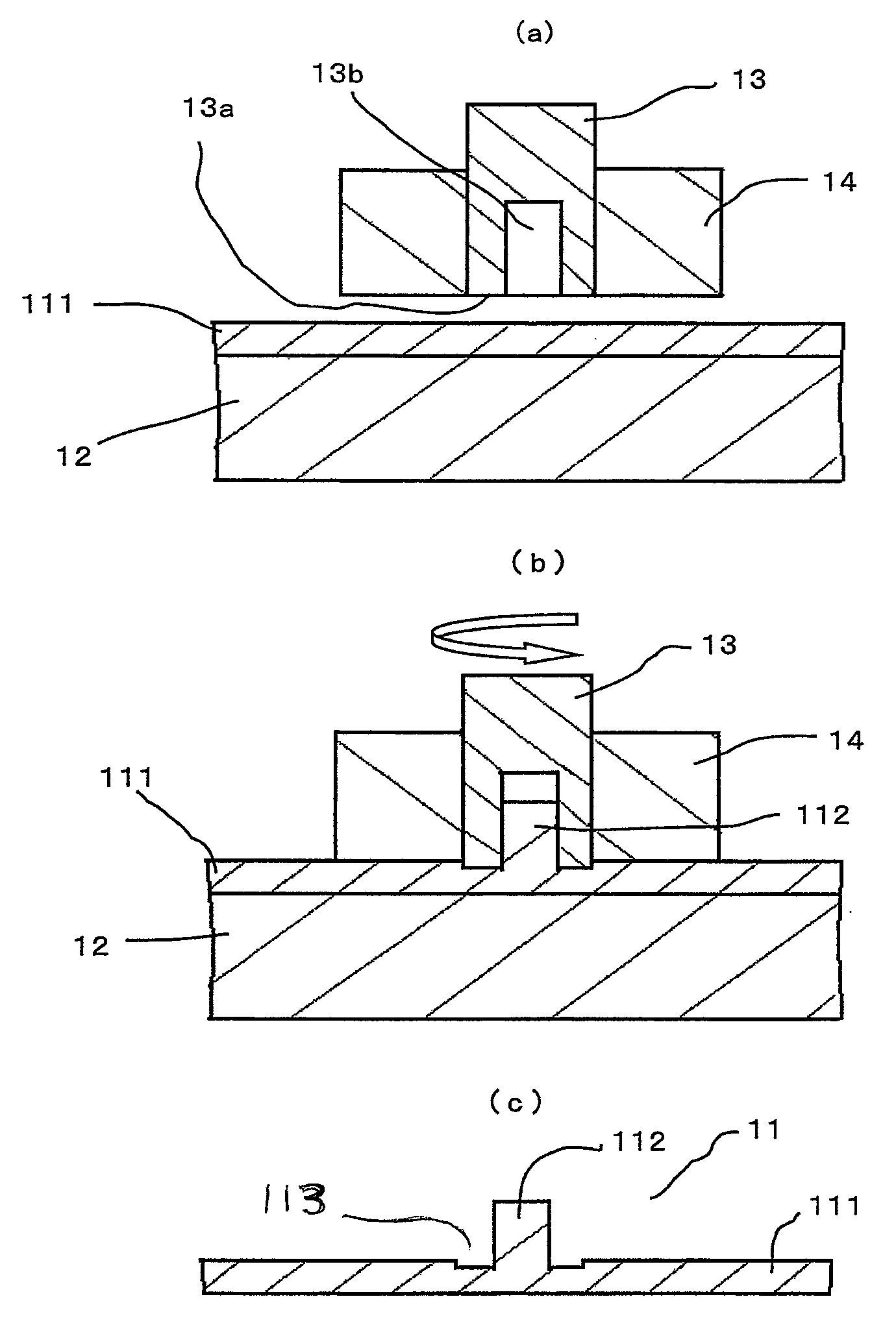
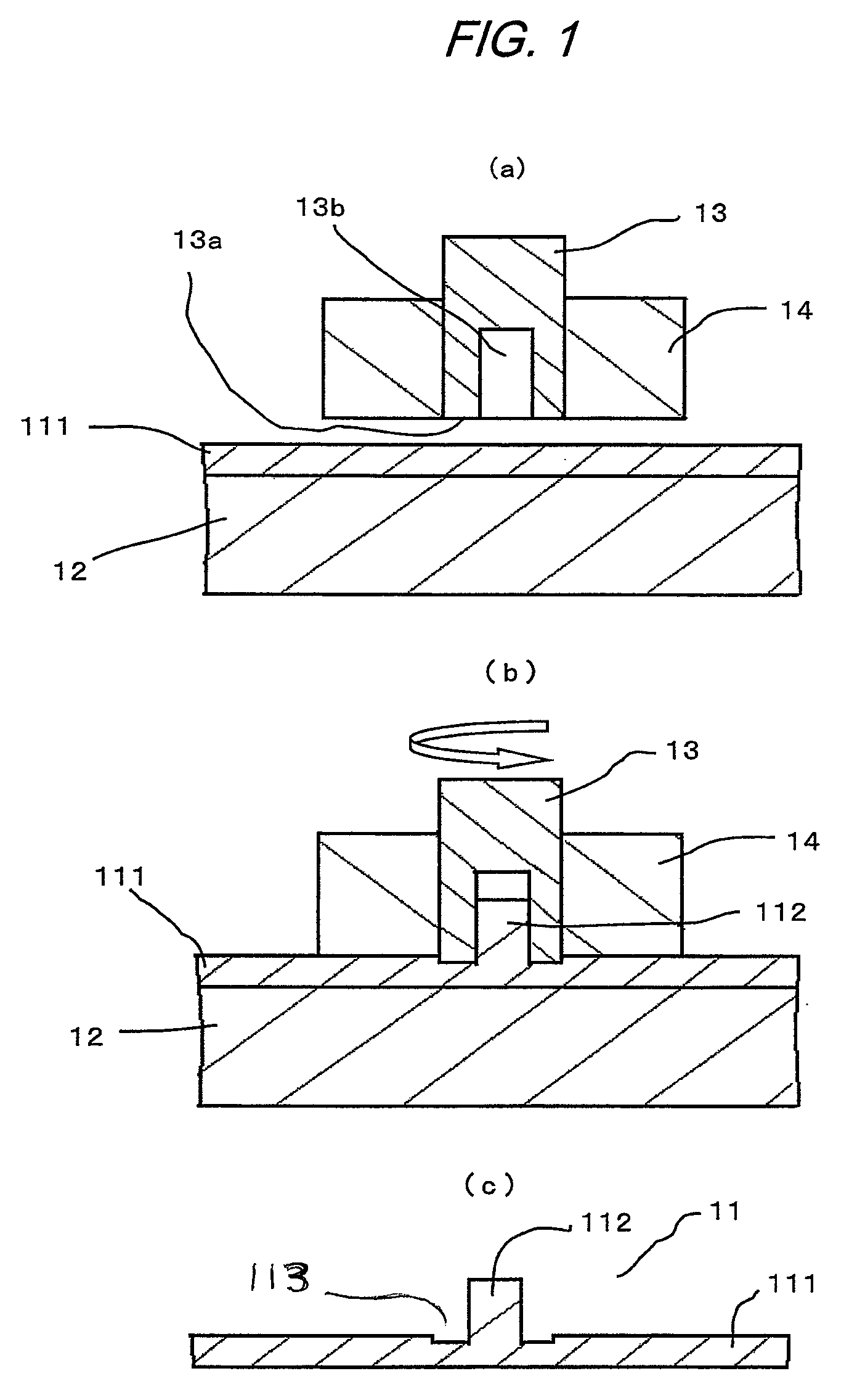
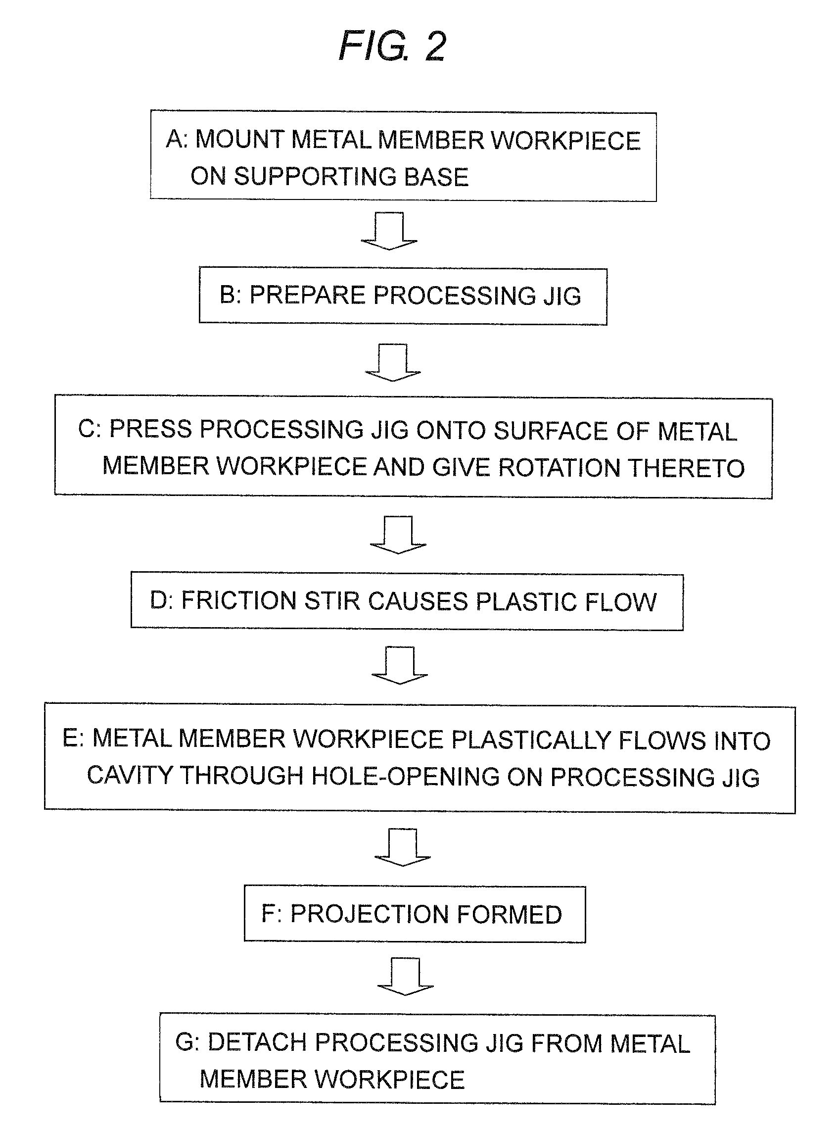
[0024]FIG. 1 and FIG. 2 are schematic diagrams of processing to illustrate the method of forming a projection on a metal member in an embodiment of the present invention. In FIG. 1, numeral 111 denotes a metal member workpiece on which a projection is to be formed; numeral 12 a processing table on which the metal member workpiece 111 is mounted and fixed; numeral 13 a processing jig having a hole-opening 13b at its distal end 13a, wherein the external shape of the jig 13 is such that the cross section thereof is circular; and numeral 14 a holding jig that holds the processing jig 13. The processing jig 13 is rotated by a rotary drive source and has a means for pressing in the direction of the distal end 13a with a predetermined thrust velocity and pressure. Forming the projection on the metal member workpiece 111 is as follows: The metal member workpiece 111 is placed on the processing table 12 at the predetermined position and fixed thereon mechanically or electro-statistically or ...

embodiment 2

[0031]FIG. 7 is schematic front and side views of an example of the projection-forming device to be used for implementing the method of forming a projection on a metal member according to the present invention. In the figure, numeral 51 denotes a base on which the device is mounted; numeral 52 a frame secured on the base 51; numeral 53 a work-holding head retained on the frame 52 movably in the XY-directions on the horizontal plane; numeral 531 a temperature and pressure sensor embedded near the surface of the work-holding head 53; and numeral 54 a driving shaft driven by a driving motor, not illustrated, to move the work-holding head 53 vertically.

[0032]Numeral 55 denotes a work holder supported on the work-holding head 53; numeral 56 a rotary tool comprised of the processing jig 13 and the holding jig 14; numeral 57 a tool holder that holds the rotary tool 56; numeral 58 a tool holder driving motor that retains the tool holder 57 and moves the tool holder 57 in the vertical direct...

embodiment 3

[0035]FIG. 8 is a schematic cross sectional diagram to show a modification example of the processing jig. In this embodiment, the processing jig 13 illustrated in FIG. 1 is comprised of: a cylindrical member 131 having a hole 131a that corresponds to the hole-opening 13b, a pressure member 132 being inserted in the hole 131a on the cylindrical member 131, and a spring 133 to press the pressure member 132 toward the distal end 13a of the cylindrical member 131 guided by the hole 131a of the cylindrical member 131. The configuration of the processing jig 13 in this manner offers effects of:[0036](1) an air escape is provided while forming the projection since a small gap is formed between the hole 131a of the cylindrical member 131 and the pressure member 132, and[0037](2) a projection having a flat-shaped distal end can be formed because the distal end of the projection is pressed during forming the projection.


PUM

PropertyMeasurementUnit
heightsaaaaaaaaaa
heightsaaaaaaaaaa
diametersaaaaaaaaaa

Abstract

The present invention provides a method of forming a solid projection having excellent mechanical properties on a metal member without supplying thermal energy from the outside, and a projection-forming device and a metal part having a projection manufactured thereby. The means for solving the problems is characterized in that the means is comprised of the processes of pressing the distal end 13a of the processing jig 13 having the hole-opening and a cavity 13b at the distal end against the surface of the metal member workpiece 111 and rotating the metal member workpiece 111 and the processing jig 13 in the direction relatively counter to the other to generate friction heat causing thereby plastic flow into the cavity through the hole-opening 13b.

Description

BACKGROUND OF THE INVENTION[0001]The present invention relates to a method of forming a projection (or projections) on a metal member by means of a new kind of the friction stir processing and a projection-forming device, wherein the projection is of the same material as the metal member; and relates to a metal part that is processed by the method of forming a projection.[0002]A technique of forming a solid projection (a boss) on the surface of a metal member has been widely used as a means for positioning, supporting, fixing or securing, or cooling. The technique is now an indispensable technology in, such as, mobile information terminals like mobile telephones and mobile personal computers, home appliances, automotive parts, and railway cars. A known and currently in-use method of forming a solid projection on the surface of a metal member includes a method such that a projection-part provided in advance is welded, blazed, solid-phase welded, or friction bonded onto a metal member...

Claims


Application Information

Patent Timeline
Patent Type & Authority Patents(United States)
IPC IPC(8): B23K20/12B21J5/06B21J5/12B21K23/00
CPCB21J5/063B21J5/12B21K23/00B23K20/126B23K20/127B23K20/129B23K2203/08Y10T29/49826Y10T29/53Y10T428/12375B23K2103/10B23K2103/15Y10T428/12389
Inventor YAMANOI, SYUICHIMOTOHASHI, YOSHINOBUYUKUTAKE, EITARO
Owner YAMANOISEIKI
Learn More