Passive heat extraction and electricity generation

a passive heat extraction and electricity generation technology, applied in mechanical equipment, lighting and heating equipment, machines/engines, etc., can solve the problems of subterranean environmental pollution of water reservoirs, natural or artificial replenishment of mined fluid, and inability to artificially replace mined fluid through reinjection, etc., to facilitate thermal energy transfer, increase contact surface area, and increase heat exchange efficiency

Active Publication Date: 2015-09-01
SCHWARCK STRUCTURE
View PDF106 Cites 14 Cited by
  • Summary
  • Abstract
  • Description
  • Claims
  • Application Information

AI Technical Summary

Benefits of technology

[0010]In some aspects, the outer casings of the vertical transfer section and the angled well are operably connected, as are the respective inner tubings. In some aspects, at least a portion of the outer casing of the vertical transfer section in the vertical well and / or the passive heat transfer device have at least one enhanced outer surface to increase the contact surface area with the subterranean material and thus increase the efficiency of the heat exchange within the desired subterranean zone.
[0011]In some aspects of the present invention, the vertical transfer section and / or the passive heat transfer device comprises an outer casing and an inner tubing arranged in a concentric configuration. The annulus between the respective outer casing and the respective inner tubing defines a first flow path for the working fluid and can facilitate transfer of thermal energy between the surrounding subterranean resource and the working fluid. The space within the respective inner tubing similarly defines a second flow path for the working fluid within the vertical transfer section and / or the passive heat transfer device and may be insulated to prevent the transfer of thermal energy between the working fluid in the first fluid path and the second fluid path. In some aspects, the inner casing of the passive heat transfer device is shorter than the outer casing within the angled portion of the well as to create a transition portion at the termination end of the passive heat transfer device such that the working fluid can be transferred between the first and second flow paths.
[0013]In some aspects of the present invention, two or more operating modes may exist in the operation of the system. In the first operating mode, cold working fluid is fed into the first fluid path where it is heated by the surrounding subterranean material (i.e. rock, soil, radioactive waste, magma, and / or any fluid material) before returning along the second fluid path. In the second operating mode, the cold working fluid can be supplied through the second fluid path before returning along the first fluid path. In addition, the operating modes can be reversed and transitioned back and forth therebetween to vary the thermal output of the heat resource as a means of controlling production when more or less consumption is required (i.e., high or low demand of energy by the consumer). For instance, the multiple operating modes allow an operator to select an operating mode to maximize the production of the passive heat transfer device by creating the maximum temperature differential between the working fluid and surrounding subterranean material to harness the most efficient heat energy during peak energy demand. Similarly, the multiple operating modes allow an operator to select an operating mode to minimize or otherwise reduce the rate of heat transfer between the passive heat transfer device and the surrounding subterranean material by creating the desired degree of temperature differential between the working fluid and surrounding subterranean material and thereby harness the desired amount of heat energy during non-peak energy demand. By controlling the location of the harnessed heat energy, the amount of heat energy can be varied and adjusted to optimize the lifetime of the subterranean thermal reservoir.
[0018]The plurality of passive heat transfer devices can be operated simultaneously or individually depending on the conditions within the subterranean zone and the consumption requirements. The independently operable passive heat transfer devices permit the operator to control the amount of thermal energy that is harnessed by the system within one or more subterranean thermal reservoirs. In some aspects in this configuration, a plurality passive heat transfer devices with shorter angled extensions can be used instead of a single passive heat transfer device with a longer angled extension. In some aspects, the angled extensions of the passive heat transfer devices are oriented in such a manner as to maximize the heat extraction from a given subterranean heat resource or various subterranean heat resources. In some aspects, the angled extensions of each of the passive heat transfer devices are oriented in a perpendicular configuration with an advective flow of the subterranean reservoir.

Problems solved by technology

An inherent drawback of these approaches is that the mined fluid taken from the reservoir must be naturally or artificially replenished to maintain flowrates and decrease land subsidence.
Artificially replacing the mined fluid through reinjection is typically undesirable as a significant portion of the energy collected must be devoted to pumping replacement fluid back into the reservoir creating a large parasitic load.
Other drawbacks in the mining and replenishment of the subterranean natural resources includes seismic risks, subsurface disturbance causing subterranean environmental pollution of water reservoirs, scaling in the wells, poor efficiencies, the need for replenishing the working fluid lost during normal operation, the need for sufficiently permeable aqueous reservoirs, and the like.
Due to the in situ fluid requirements, the current state of the art is only able to operate in areas where in situ reservoir fluid is present.
Also, the current state of the art of subterranean heat energy extraction is limited by the temperatures in which it may operate and therefore is only capable of extracting heat from a small fraction of the overall available subterranean heat resource.
However, the current closed-loop apparatus approaches have drawbacks relating to efficient collection of the subterranean heat energy, controlling the rate of energy production, and maximizing productivity over a period of time to sustain the heat resource, among others.
Unlike other types of power generation such as gas fired power generation, adjusting the production rate of energy harnessed from subterranean heat utilizing the current state of the art can be exceedingly difficult as the production rate is largely dependent on the uncontrollable conditions within the subterranean zone.

Method used


Image

  • Passive heat extraction and electricity generation
  • Passive heat extraction and electricity generation
  • Passive heat extraction and electricity generation

Examples


Embodiment Construction

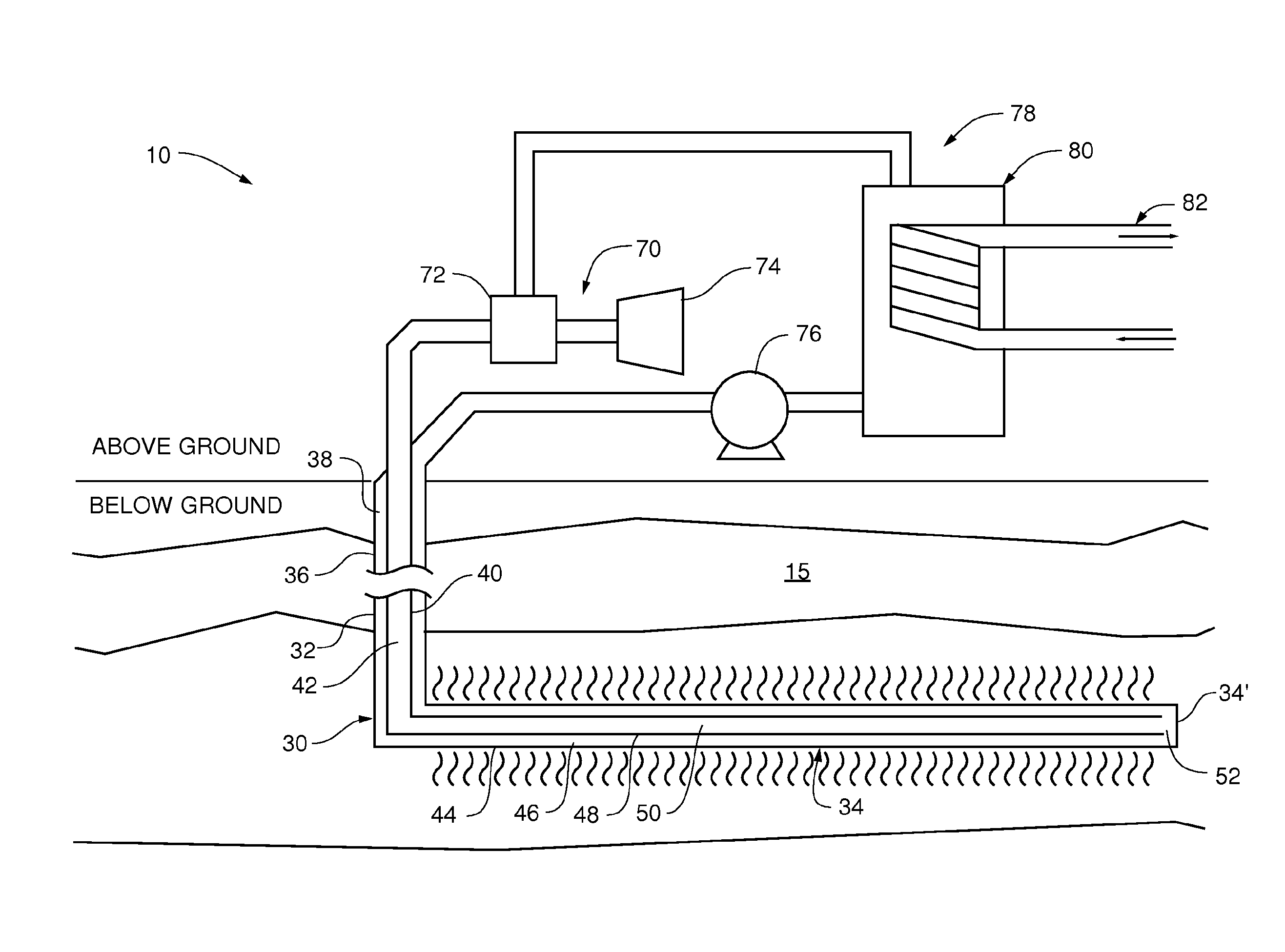
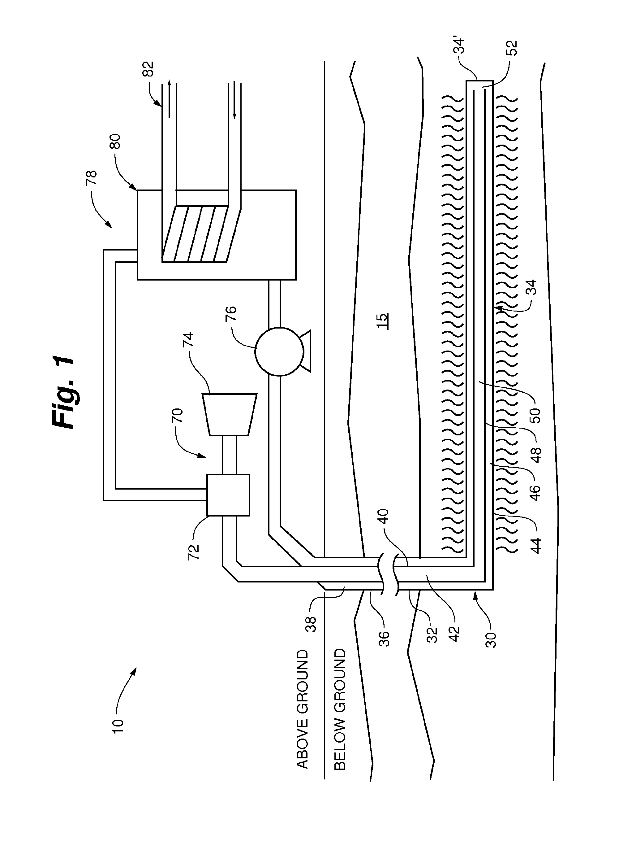
[0045]As shown in FIG. 1, according to an aspect of the present invention, a wellbore at least partially extending through to a heated subterranean zone is coupled in fluid flow communication to a power production facility so as to form a closed-loop system 10. A working fluid can circulate through the closed-loop system 10 thereby facilitating the conversion of the produced energy into other useful forms of energy.

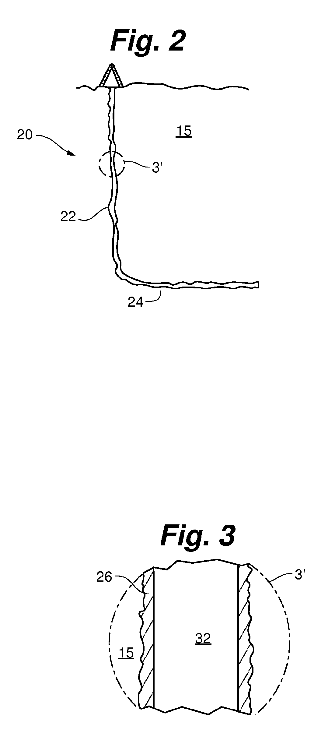
[0046]As shown in FIGS. 1-5, according to an aspect of the present invention, a system 10 for harnessing thermal energy from a subterranean zone generally comprising a well bore 20, a bi-directional transfer pipe 30 within the well bore 20, and an output apparatus 70. In some aspects, the well bore 20 comprises a substantially vertical wellbore section 22 and at least one angled wellbore section 24 extending from the vertical wellbore section 22 in a substantially horizontal configuration into one or more desired subterranean zones 15.

[0047]As shown in FIGS. 1-5 and 14, t...


PUM


Abstract

A closed-loop heat exchange system and related methods for harnessing subterranean heat energy from a subterranean zone having a passive heat transfer device with multiple operational modes for targeting hotspots within the subterranean zone and adjusting the rate of energy harnessed according to consumption demands. The system can also have at least one enhanced surface section for increasing the heat exchange efficiency and / or a variable pump for controlling the rate at which the working fluid travels through the passive heat transfer device.

Description

PRIORITY CLAIM[0001]The present application is a National Phase entry of PCT Application No. PCT / US2011 / 064425, filed Dec. 12, 2011, which application claims priority to U.S. Provisional Application No. 61 / 421,996 entitled “PASSIVE HEAT EXTRACTION AND ELECTRICITY GENERATION,” filed Dec. 10, 2010, which applications are hereby incorporated by reference in their entirety.FIELD OF THE INVENTION[0002]The present invention is directed to a closed-loop passive heat extraction system and methods for producing energy from subterranean heat reservoirs. Specifically, the present invention is directed to a passive heat transfer apparatus for exchanging heat between a working fluid and one or more naturally occurring or manmade subterranean heat reservoirs in subterranean material.BACKGROUND OF THE INVENTION[0003]Subterranean heat energy has recently received increased attention as a source of environmentally friendly and renewable energy. Currently, subterranean heat energy is harnessed by bor...

Claims


Application Information

Patent Timeline
Patent Type & Authority Patents(United States)
IPC IPC(8): F03G7/00F24J3/08F03G7/04
CPCF03G7/04F24J3/08F24J3/084Y02E10/125F24T10/10F24T10/17F24T10/40Y02E10/10Y02P80/10
Inventor SCHWARCK, MATTHEW N.
Owner SCHWARCK STRUCTURE
Why Eureka
Try Eureka