
Surveying and leveling device

a leveling device and leveling technology, applied in the direction of surveying, height/levelling measurement, instruments, etc., can solve the problems of large time and monetary expenditure, large error detection, and the inability to recognize errors, so as to facilitate the transport of the assembled device, increase accuracy, and facilitate the effect of disconnection and adjustmen

Inactive Publication Date: 2015-09-01
RM ASSET GRP
View PDF8 Cites 0 Cited by
  • Summary
  • Abstract
  • Description
  • Claims
  • Application Information

AI Technical Summary

Benefits of technology

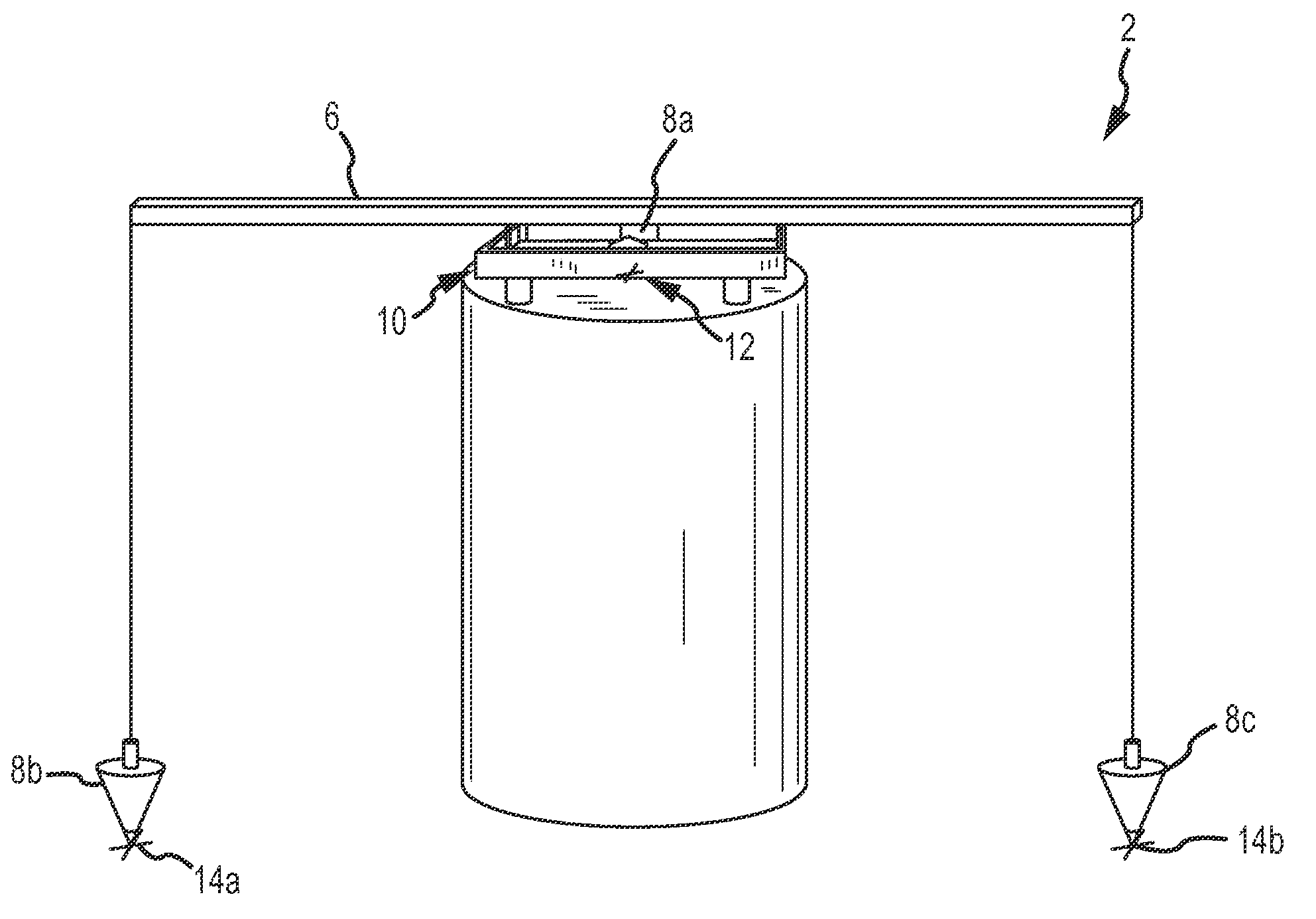
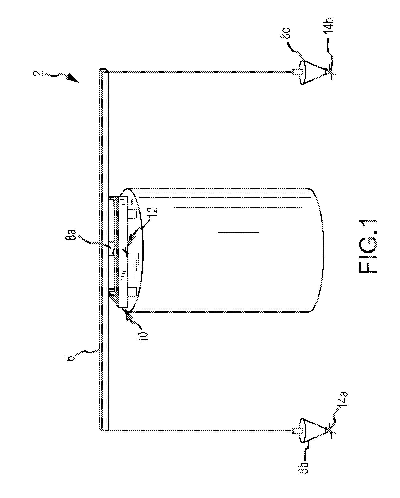
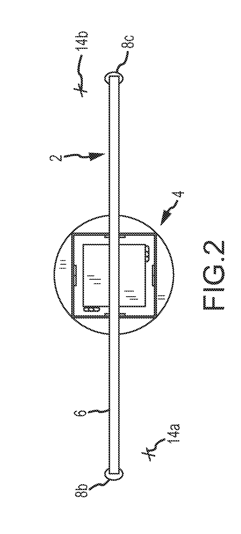
[0008]In one embodiment, the present invention comprises a substantially rigid member having a first end and a second end and a plurality of plumb bobs attached thereto. For example, three plumb bobs may be distributed substantially evenly across a length of the substantially rigid member with first and second plumb bobs extending from a first end and a second of the member respectively and a third bob extending from a point substantially equidistant from the first and second ends. The third bob may be aligned or positioned over a reference point (e.g. a centered indentation) on a feature to be measured or installed. The first and second bobs will therefore be positioned at opposing points away from the center of the feature. The length of the rod, as will be recognized, extends beyond a predetermined radius of the feature to be installed and provides for increased radius and increased accuracy in the radial positioning of the feature.
[0012]In preferred embodiments, one or more plumb bobs are connected to the substantially rigid member via a string or wire, the string or wire being selectively adjustable in at least a vertical direction. Such adjustability allows for the bobs to be raised or lowered to a desired position, such as a position in close proximity with a reference point (e.g. a measured / surveyed point marked on the ground) in order to increase accuracy of measurements.
[0018]Provided on the mount or bracket assembly is one or more receiving means for receiving and securing a rigid member. In various embodiments, receiving means comprise colored features to allow for ease of differentiation by a user when viewed through various surveying equipment or at a distance.
[0019]Securing means, including one or more straps comprising hook and loop securing features, are provided on the mount to secure one or more rigid members and allow ease of transport of an assembled device. Securing means also enable quick disconnect and adjustment of a rigid member, as may be necessary or desirable to accommodate various different bolt patterns provided on different features.
[0020]In one embodiment, a surveying device comprising a mount unit and a rigid member extending therefrom is of one-piece construction. Such a device may be manufactured with (for example), the aid of computer numerical control (CNC) to increase accuracy and allow ease of assembly.

Problems solved by technology

For example, in high precision operations such as the construction of airport runways and various related features, regulations imposed by various government agencies may require that certain features be permanently installed with a very small margin of error.
Typically, if such features are installed improperly, error is not recognized until after the feature is encased in large amounts of concrete.
Corrective actions are therefore complicated and require substantial time and monetary expenditures.
Current methods and systems for measuring and installing features with high levels of accuracy comprise significant amounts of guess-and-check work, numerous measurements and calculations from known surveying features, and are typically time consuming.
Such methods and systems therefore typically consume unnecessary man hours and unduly protract the duration of activities already subject to significant time constraints.

Method used


Image

  • Surveying and leveling device
  • Surveying and leveling device
  • Surveying and leveling device

Examples


Embodiment Construction

[0034]The present invention has significant benefits across a broad spectrum of endeavors. It is the applicant's intent that this specification and the claims appended hereto be accorded a breadth in keeping with the scope and spirit of the invention being disclosed despite what might appear to be limiting language imposed by the requirements of referring to the specific examples disclosed. To acquaint persons skilled in the pertinent arts most closely related to the present invention, a preferred embodiment of the method that illustrates the best mode now contemplated for putting the invention into practice is described herein by, and with reference to, the annexed drawings that form a part of the specification. The exemplary method is described in detail without attempting to describe all of the various forms and modifications in which the invention might be embodied. As such, the embodiments described herein are illustrative, and as will become apparent to those skilled in the ar...


PUM


Abstract

A surveying and measuring device and method of using the same is provided. The device, which is particularly suited for determining or measuring a rotational position of an object, comprises an elongate rigid member extending radially away from a known center of an object. Distal ends of the rigid member downwardly project points which may be compared to, for example, survey markers or known points.

Description

[0001]The present application claims the benefit of priority from U.S. Provisional Patent Application No. 61 / 539,054, filed Sep. 26, 2011, the entire disclosure of which is hereby incorporated by reference in its entirety.FIELD OF THE INVENTION[0002]The present invention relates generally to devices and methods for use in surveying and related installation or construction. More specifically, the present invention relates to devices and methods for measuring, leveling, centering, and / or orienting various objects with respect to a predetermined reference point.BACKGROUND[0003]In various installation and construction operations, it is often necessary to position various features with a high degree of accuracy. For example, in high precision operations such as the construction of airport runways and various related features, regulations imposed by various government agencies may require that certain features be permanently installed with a very small margin of error. The Federal Aviatio...

Claims


Application Information

Patent Timeline
Patent Type & Authority Patents(United States)
IPC IPC(8): G01D21/00G01C9/16G01C9/02G01C15/10G01C9/26G01C1/02G01C5/00G01C19/00G01C17/00G01B11/275G01C9/10G01C9/24G01C9/00
CPCG01C9/02G01C9/16G01C9/10G01C9/24G01C9/26G01C15/10
Inventor BAKER, JOHN D.BAKER, REED W.GREGORY, MICHAEL J.
Owner RM ASSET GRP
Learn More