
Optical film and display device having the same

a technology of optical film and display device, applied in the field of optical film, can solve the problems of complicated design of conventional optical film, and achieve the effect of increasing the light emergent angl

Inactive Publication Date: 2015-09-01
AU OPTRONICS CORP +1
View PDF5 Cites 10 Cited by
  • Summary
  • Abstract
  • Description
  • Claims
  • Application Information

AI Technical Summary

Benefits of technology

The patent describes an optical film that can increase the amount of light that comes out of it by using microstructures. This film is easy to manufacture and can effectively control the range of light angles that come out of it. When combined with a liquid crystal display panel and a backlight module, the optical film can create a display that has a wide viewing angle.

Problems solved by technology

However, the design of conventional optical films is very complicated.

Method used


Image

  • Optical film and display device having the same
  • Optical film and display device having the same
  • Optical film and display device having the same

Examples


Embodiment Construction

[0027]The embodiments of the present disclosure provide an optical film which is preferably applied to enhance the optical characteristics, such as increasing the light emergent angle from the light output face. In a preferred embodiment, the optical film is applied to a display device to increase the viewing angle of the display device. The optical film is preferably made of polymer or glass in an integral form. However, in other embodiments, the optical film can be made of other materials and by other methods.

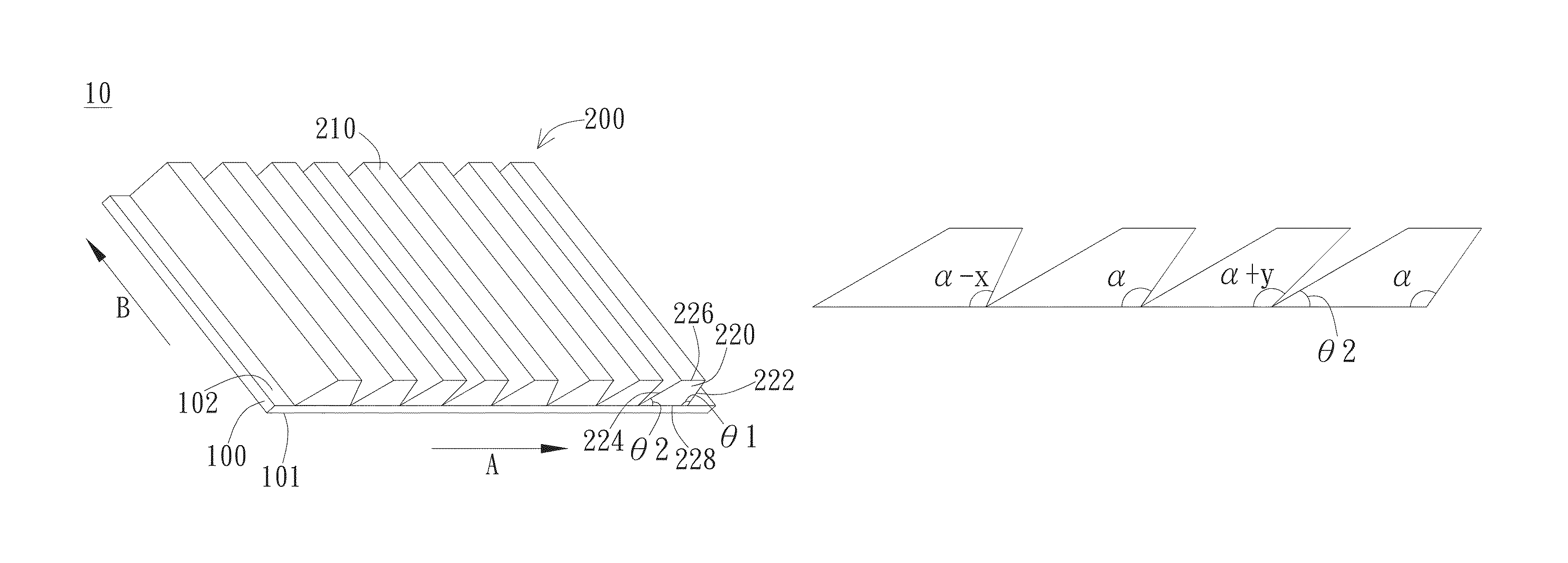
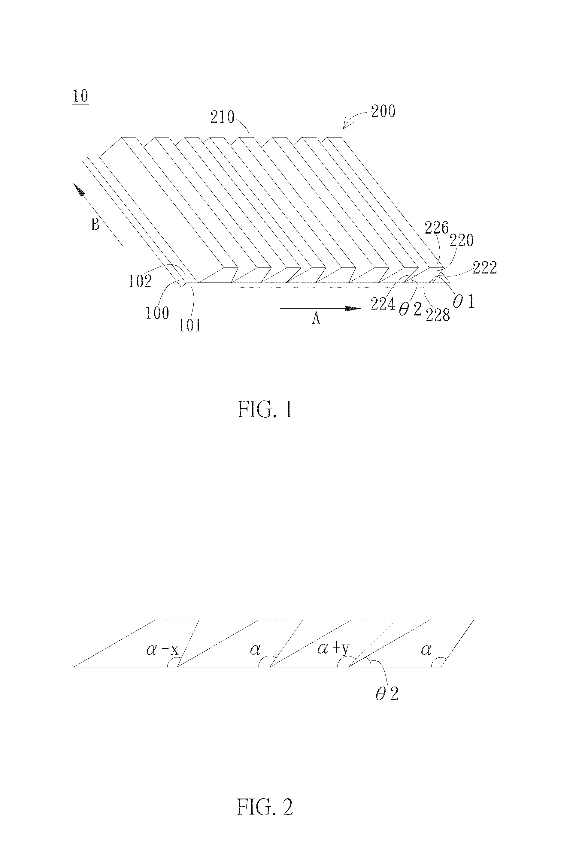
[0028]In the embodiment of FIG. 1, the optical film includes a light input face 101, a light output face 102, and a light-output structure 200, wherein the light output face 102 is parallel and opposite to the light input face 101. That is, the light input face 101 and the light output face 102 are two opposite surfaces of the film body 100. In a preferred embodiment, the film body 100 has a rectangular shape. However, the film body 100 can have other suitable shapes accordin...


PUM

PropertyMeasurementUnit
obtuse angleaaaaaaaaaa
acute angleaaaaaaaaaa

Abstract

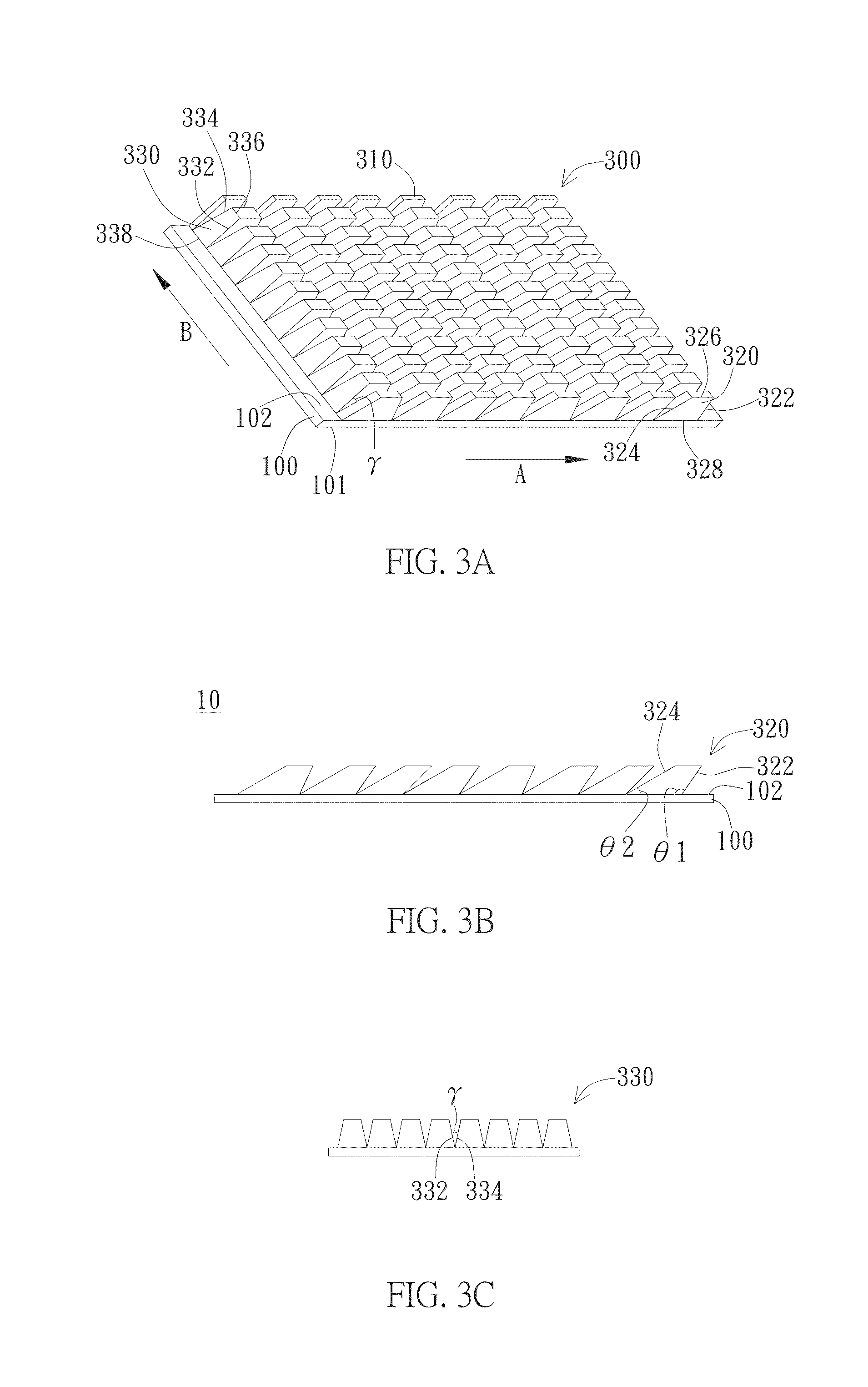
An optical film and a display device having the same are provided. The optical film has a light input face, a light output face opposite to the light input face, and a light-output structure disposed on the light output face. The light-output structure includes a plurality of light output microstructures such as prisms disposed side by side along a first direction on the light output face. Each prism has a first quadrilateral cross section parallel to the first direction. A first side of the quadrilateral cross section is connected to the light output face and includes a first angle with the light output face, wherein the first angles of the prisms continuously arranged have angle values varying in a periodic manner.

Description

BACKGROUND[0001]1. Technical Field[0002]The present disclosure generally relates to an optical film. Particularly, the present disclosure relates to an optical film having light-output microstructures arranged in a periodic manner and a display device having the optical film.[0003]2. Description of the Prior Art[0004]In recent years, flat display devices have been widely used in a variety of fields as an independent display device or embedded in electronic devices for displaying information. There are all kinds of flat display devices including, for example, organic light-emitting diode display device, liquid crystal display device, electrophoretic display device, etc. Among them, liquid crystal display device is the most common flat display device.[0005]For liquid crystal display device, the operation principle is to utilize the orientation of liquid crystal molecules in the liquid crystal display panel to control the transmission of backlight for each pixel so as to display images...

Claims


Application Information

Patent Timeline
Patent Type & Authority Patents(United States)
IPC IPC(8): G02F1/1335G02B5/04
CPCG02B5/045G02F1/1335G02B6/0053G02F1/133524
Inventor YAN, JINXU, DA-MINGCHENG, HUI-CHUANWU, SHIN-TSONLAN, YI-FENTSAI, CHENG-YEH
Owner AU OPTRONICS CORP
Learn More