Separator and fuel cell using that separator

a separator and separator technology, applied in the field of separators and fuel cells, can solve the problems of difficult operation that requires extreme skill, difficult to ensure the contact area and the air flow at the same time, and the same structure will pose problems, so as to achieve the effect of reducing power collection resistance, high degree of skill, and reducing the manufacturability of not only the separator, but also the fuel cell

Active Publication Date: 2005-10-06
EQUOS RES
View PDF17 Cites 17 Cited by
  • Summary
  • Abstract
  • Description
  • Claims
  • Application Information

AI Technical Summary

Benefits of technology

[0021] It is particularly effective to have the single cell of this structure be formed by sandwiching the polymer electrolyte membrane between carbon cloth via a catalyst layer; and the gas diffusion portions be structured such that the distance between edges of adjacent air holes is equal to, or less than, 0.3 mm in order to reduce the area over which water produced by the single cell adheres and disperse the pressure toward the carbon cloth over the entire surface.
[0022] According to the present invention, the gas diffusion portions and the spacer portions which form the separator are formed integrally by bending the wire mesh member in the shape of a corrugated plate. As a result, the area of the gas supply passage is determined by the height of the waves of the wire mesh member, and the air flow and diffusivity are determined, irrespective of the wave height, by the fineness of the mesh of the wire mesh member. Therefore, according to this structure, the aperture ratio of the portion which covers the surfac...

Problems solved by technology

Since the moisture from only the water produced by the electrolytic reaction is generally not sufficient, it is necessary to provide a mechanism to supply humidifying water to each MEA.
As a result, it is considered difficult to ensure both the contact area and the air flow at the same time.
Next, with the related technology disclosed in Japanese Patent Laid-Open Publication No. 7-254424, because the structure has holes for supplying gas provided only at the top portion of the thin collector plate that is in contact with the anode or cathode, the machining for opening the holes in the collector plate is done at the top portion of the waves, which is approximately only several millimeters wide, so it is considered a difficult operation that requires extreme skill.
Also, even if a structure in which holes are provided only at the top portion of the waves, as described above, can be applied with no problem to a fused carbonate fuel ce...

Method used


Image

  • Separator and fuel cell using that separator
  • Separator and fuel cell using that separator
  • Separator and fuel cell using that separator

Examples


first embodiment

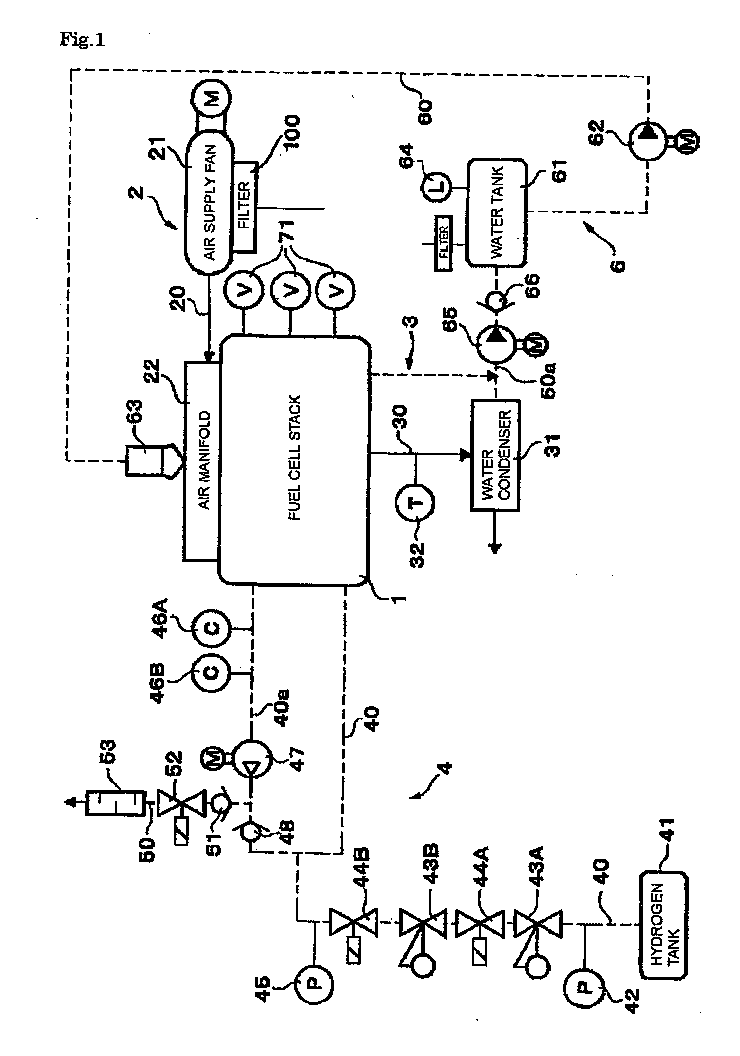
[0037] Hereinafter, exemplary embodiments of the present invention will be described with reference to the appended drawings. First, FIGS. 1 to 7 illustrate a first exemplary embodiment of the present invention. FIG. 1 is an example of a diagram of a vehicular fuel cell system which uses a fuel cell stack 1 according to one application of the present invention. The fuel cell stack 1 serves as the main component of the fuel cell system which also includes a fuel cell main portion, a fuel supply system 4, and a water supply system 6. The fuel cell main portion includes i) an air supply system (indicated by the solid lines in the drawing) 2 including an air fan 21 which serves as an air supply mechanism that supplies air to the fuel cell stack 1, and ii) an air exhaust system 3 including a water condenser 31. The fuel supply system 4 (indicated by the alternate long and two short dashes line in the drawing) includes a hydrogen tank 41 which serves as a hydrogen supply mechanism. The wa...

second embodiment

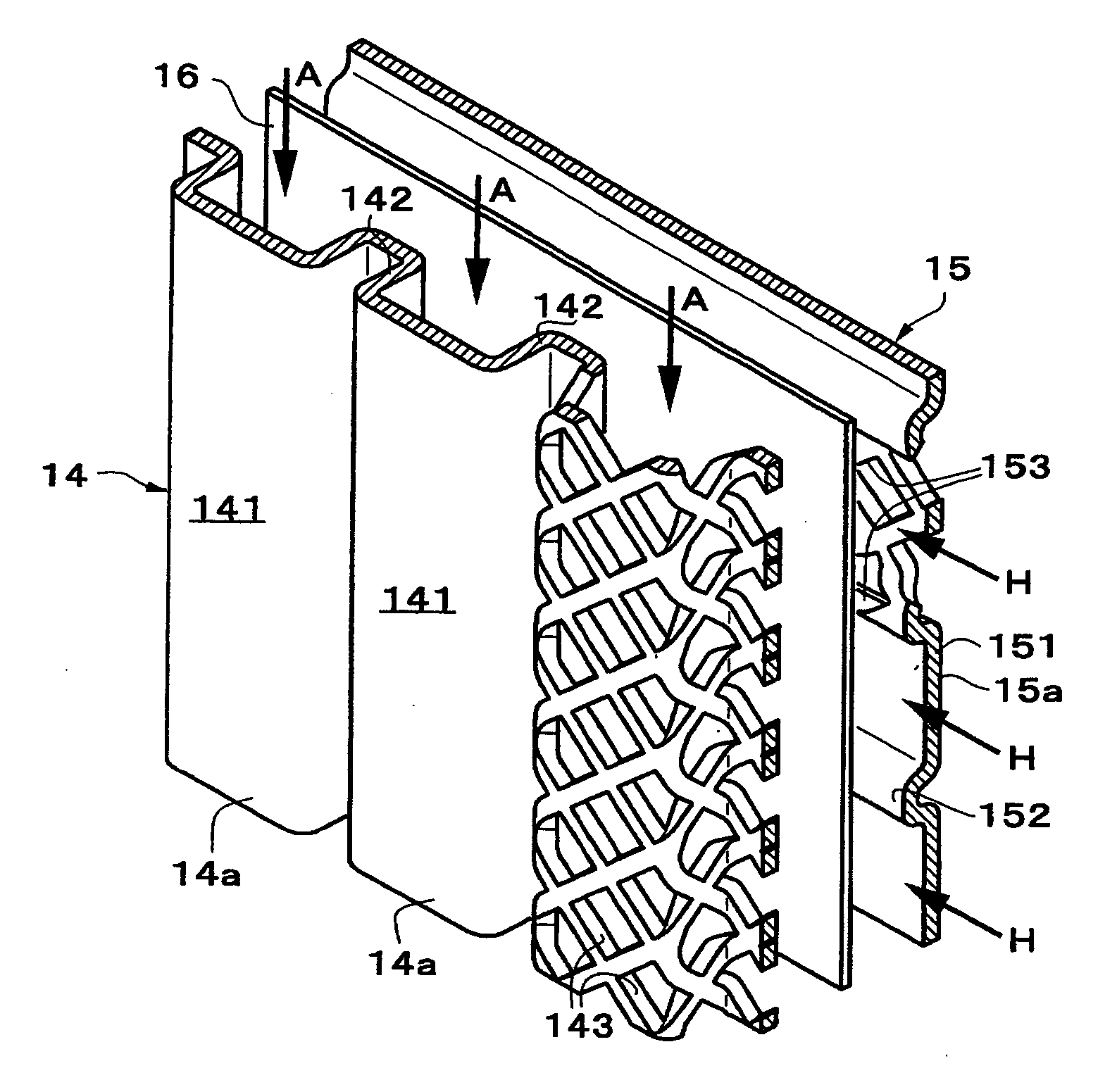
[0071] A second exemplary embodiment shown next in FIG. 9 has the same wave dimensions, i.e., wave height and pitch, as does the collector 15 on the fuel electrode side in the first exemplary embodiment in order to be able to use the same material of the collectors 14 and 15. When this structure is employed, protrusions 16a that protrude toward the collector 14 side are formed on the separator substrate 16 at a pitch that matches the pitch at which the bottom portions of the collector 14 are arranged, such that the separator substrate 16 is also a wavy plate shape in order to ensure the flow path sectional area on the air electrode side where the wave height is lower. Hereinafter, portions in this exemplary embodiment that are the same as those in the first exemplary embodiment will be denoted by the same reference numerals, and descriptions of those portions will be omitted. Only those parts that differ from the first exemplary embodiment will be described here.

[0072] The height o...

third embodiment

[0075] The example shown next in FIG. 10 is an example in which the collector 15 on the fuel electrode side is formed with a flat mesh member with no waves which is outside of the application of the present invention. With this example, the separator substrate 16 is formed of a wavy plate that forms continual protrusions 16a and 16b that protrude to both the air electrode side and the fuel electrode side with respect to a reference surface of the substrate. All other structure is the same as that in the second exemplary embodiment, with like portions denoted by like reference numerals. Descriptions thereof would be redundant and so will be here.


PUM


Abstract

A separator of a fuel cell, which is inserted between single cells, each single cell having an electrolyte sandwiched between electrodes, in order to stack the single cells together, includes gas diffusion portions which are arranged so as to cover a surface of the electrodes and in which are formed multiple air holes for gas diffusion, and spacer portions which form parallel divided gas passages on the back side of portions of the gas diffusion portions which cover the surface of the electrodes. The gas diffusion portions and the spacer portions are integrally formed by bending a wire mesh member to have a rectangular corrugated plate shaped cross-section. As a result, the air holes are formed evenly between the electrodes and the separator and high contact pressure is ensured by the contact of the fine wire mesh, thereby making it possible to both have the gas diffuse evenly and reduce the power collection resistance.

Description

BACKGROUND OF THE INVENTION [0001] 1. Field of the Invention [0002] The present invention relates to a fuel cell, and more particularly, to a separator interposed between single cells of a fuel cell. [0003] 2. Description of the Related Art [0004] Various types of fuel cells exist, one of which is a polymer electrolyte fuel cell that is particularly well suited for use in vehicles due to its small size which is made possible by a low reaction temperature. This type of fuel cell is based on units of membrane electrode assemblies (MEAs), each MEA having a polymer electrolyte membrane sandwiched between two gas diffusion electrodes (each of which includes a catalyst layer and a porous support layer (i.e., a gas diffusion layer)). A separator that also acts as a supply channel for reaction gases such as hydrogen (i.e., the fuel gas) and oxygen (i.e., the oxidizing gas) is arranged on the outside of each membrane electrode assembly. The separator both acts as an impermeable barrier for t...

Claims


Application Information

Patent Timeline
IPC IPC(8): H01M2/02H01M8/04H01M8/00H01M8/02H01M8/10H01M2/14H01M2/00
CPCH01M8/0254H01M8/026H01M8/04067H01M8/04097H01M8/04164H01M8/04291H01M8/0435H01M8/04388H01M8/04447H01M8/04552H01M8/04559H01M8/04731H01M8/04798H01M8/04835H01M8/0485H01M8/241H01M8/0267Y02E60/50H01M8/02
Inventor HORIGUCHI, MUNEHISA
Owner EQUOS RES
Why Eureka
Try Eureka