Space robot gripper mechanism

A robot hand and space technology, applied in the direction of manipulators, chucks, manufacturing tools, etc., can solve the problems of non-unique locking position, easy loss of targets, small capture range, etc., to achieve compact interior, save interior space, and improve transmission. The effect of efficiency

Inactive Publication Date: 2011-05-25
BEIJING UNIV OF POSTS & TELECOMM
View PDF4 Cites 18 Cited by
  • Summary
  • Abstract
  • Description
  • Claims
  • Application Information

AI Technical Summary

Problems solved by technology

[0003] The present invention solves the problems of the existing space robot claws such as small capture range, non-unique locking position, easy loss of targets during the capture process, etc., and at the same time greatly simplifies the entire mechanism, improves the transmission efficiency of the mechanism, and improves the processing efficiency. Manufacturability has also been improved

Method used


Image

  • Space robot gripper mechanism
  • Space robot gripper mechanism
  • Space robot gripper mechanism

Examples


specific Embodiment approach 1

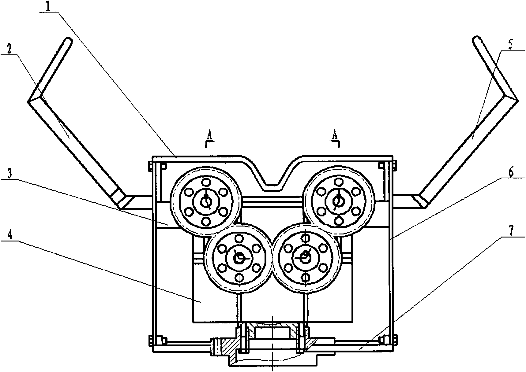
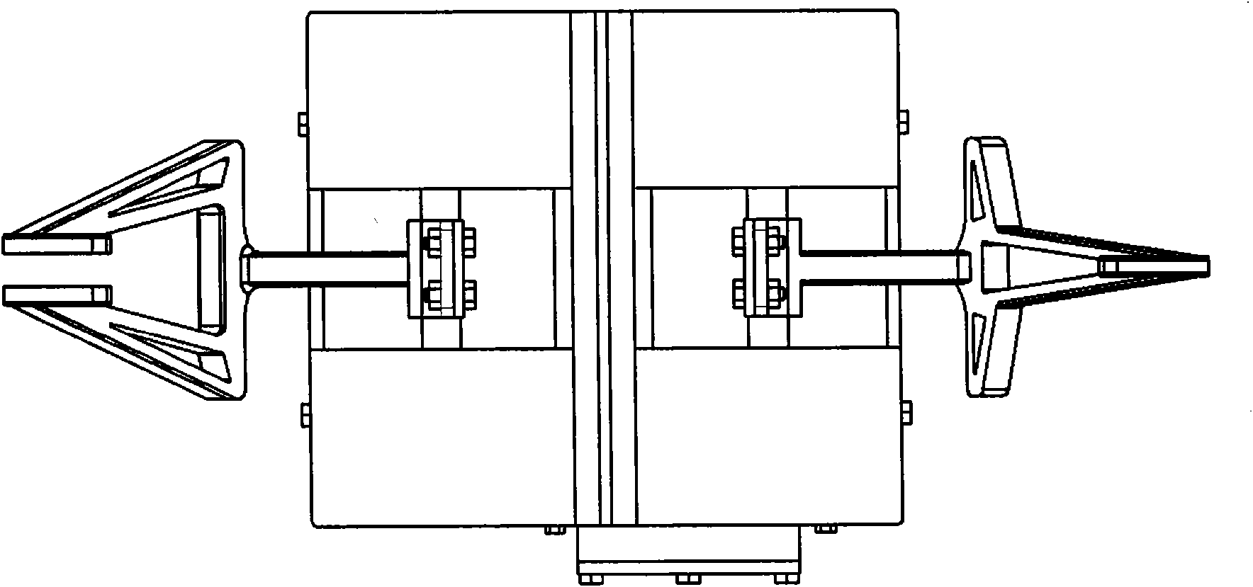
[0018] Specific implementation mode one: see figure 1 , image 3 As shown, the present invention is located at the operation end of a kind of mechanical arm, carries out the grasping operation, and its structure comprises palm surface 1, upper bearing seat 3, lower bearing seat 4 and box bottom 7 are positioned with conical pin, and bolt is fixedly connected to form this gripper The basic skeleton of the organization. Wherein the combination of the palm surface 1 and the upper bearing seat 3 constitutes the bearing seat of the second finger shaft 9 and the first finger shaft (same as the second finger shaft); the combination of the upper bearing seat 3 and the lower bearing seat 4 constitutes the motor 11 transmission Shaft and brake shaft 22 bearing housing. Its design adopts split type for easy assembly.

[0019] see Figure 4 As shown, two finger shafts 9 are installed in the bearing hole between the palm surface 1 and the upper bearing seat 3, and are positioned by end...

specific Embodiment approach 2

[0026] Specific implementation mode two: see figure 1 , image 3 , The claw mechanism transmission system is made up of motor 11, gear 19 (2), gear 21, gear 27, brake shaft 22, finger shaft 9 (2). Motor 11 is fixedly connected with bearing seat 3,4 up and down by screw, and at this moment, motor output shaft 11, finger shaft 9 (2), braking shaft 22 form four shafts parallel in pairs. The synchronous rotation of the first finger 5 and the second finger 2 is realized through the gear transmission group: that is, the gear 21 is driven by the motor 11, and through meshing with the gear 19 and the idler 27, the motion is transmitted to the finger shaft 9 and the second finger respectively One-finger finger axis (the same as the two-finger finger axis), so as to realize the synchronous opening and closing movement of two fingers.

[0027] Palm surface 1, upper bearing seat 3, lower bearing seat 4, box wall 6, box bottom 7, one finger 5, two fingers 2, finger cover plates 16 (2 pie...


PUM


Abstract

The invention discloses a space robot gripper mechanism, namely an end effector of a mechanical arm, which solves the problems of small gripping range, non-unique locking position, high probability of losing a target during griping and the like existing in the conventional gripper mechanism, greatly simplifies the entire mechanism and also improves the manufacturability. In the mechanism, a palm surface 1, an upper bearing seat 3, a lower bearing seat 4 and a box bottom 7 form a basic frame of the entire mechanism; two finger shafts 9 are arranged in bearing holes between the palm surface 1 and the upper bearing seat 3; two fingers 2 and 5 are fixedly connected with the finger shafts 9; the shaft ends of the two finger shafts are provided with gears 19; a motor 11 and a brake shaft 22 are arranged in through holes between the upper bearing seat 3 and the lower bearing seat 4; the shaft ends of the brake shaft 22 and the motor 11 are provided with gears 21; the gripper box bottom 7 is connected with the bearing seats and an external mechanism through flanges; and a box wall 6 is interconnected with the palm surface 1 and the box bottom 7 to package the entire gripper mechanism. The mechanism has the advantages of compact design, small volume, easiness of machining, convenience in assembly and disassembly and the like.

Description

technical field [0001] The invention relates to a space robot gripper and an end effector of a mechanical arm. Background technique [0002] In the future space station, robots can replace humans in maintenance work in the space environment. The operating ability and operating efficiency of the robot depend on the size of the operating ability of the robot gripper. The study of space grippers in foreign countries started earlier. From the structural division, these gripper mechanisms mainly include external grasping, internal support and other structures. The external grasping type is divided into two-finger, three-finger and multi-finger structures. At present, the more successful extravehicular two-finger grippers in the world are the Japanese ETS-7 robot grippers, and the OTCM grippers on the SPDM robot of the Canadian Space Agency. Research in this field started relatively late in my country. The Laboratory of "Micro Sensors and Special Robots" of Hefei Institute of I...

Claims


Application Information

Patent Timeline
Patent Type & Authority Applications(China)
IPC IPC(8): B25J15/08
Inventor 宋荆洲孙浩张延恒叶平贾庆轩孙汉旭高欣
Owner BEIJING UNIV OF POSTS & TELECOMM
Why Eureka
Try Eureka