Electronically controlled universal motor

a universal motor and electric motor technology, applied in the field of electric motors, can solve the problems of reducing efficiency, reducing efficiency, and reducing efficiency, so as to reduce the amount of material, reduce the thickness, and improve the effect of motor compactness

Active Publication Date: 2015-09-08
ARM LTD
View PDF24 Cites 10 Cited by
  • Summary
  • Abstract
  • Description
  • Claims
  • Application Information

AI Technical Summary

Benefits of technology

[0012]By amending the motor in this way and extending the range of speeds at which it operates efficiently the need for a gearing system is reduced or in some cases eliminated, which decreases the cost and improves the efficiency of the system. Indeed, where a variable gear set is avoided, the need for a corresponding transmission is also avoided. Complex techniques in which for example the gear variability is provided by a planetary gear set connected to a second motor are thus avoided, and such a second motor is not required.
[0034]As noted above, independent control of the power supplied to the windings on the stator and rotor provides a wide range of control possibilities for the motor. In particular the rotational force provided to the intermediate screening component can be varied in a number of different ways while still providing the windings on the respective rotor and / or stator with or close to their most efficient power loading.

Problems solved by technology

However, this high efficiency is generally restricted to a particular optimum operating frequency of the motor and when the motor moves away from this operating frequency the efficiency may drop dramatically.
The provision of gears adds cost to the system and can themselves reduce efficiency.
However, the difficulties associated with coupling the required waveforms to the rotor winding arrangements have significant drawbacks.
Although such a universal motor may provide a compact and high powered motor, the efficiency of such a motor still reduces dramatically away from an optimum operating frequency and thus, such a motor is generally operated in conjunction with some gearing mechanism.

Method used


Image

  • Electronically controlled universal motor
  • Electronically controlled universal motor
  • Electronically controlled universal motor

Examples


Embodiment Construction

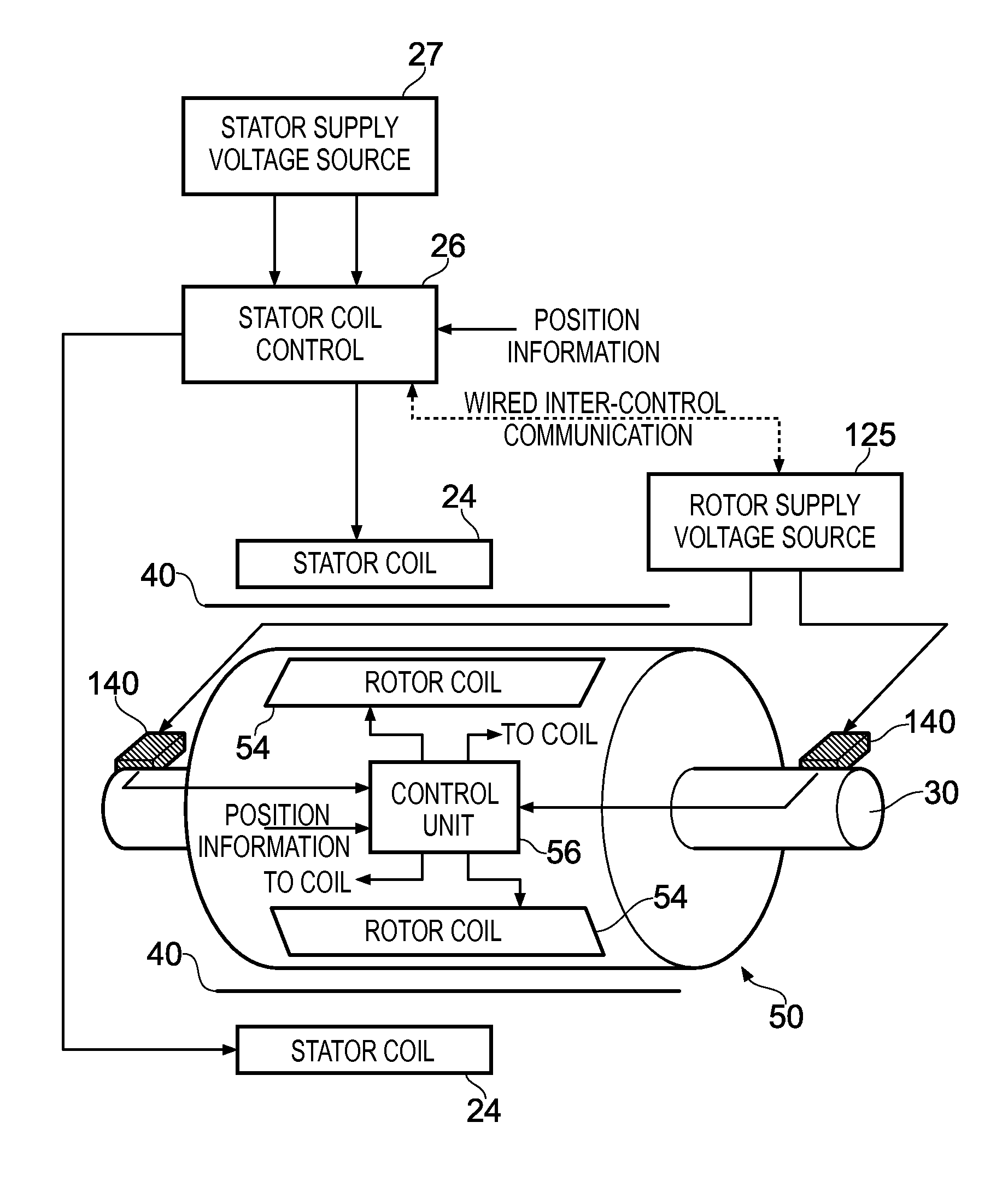
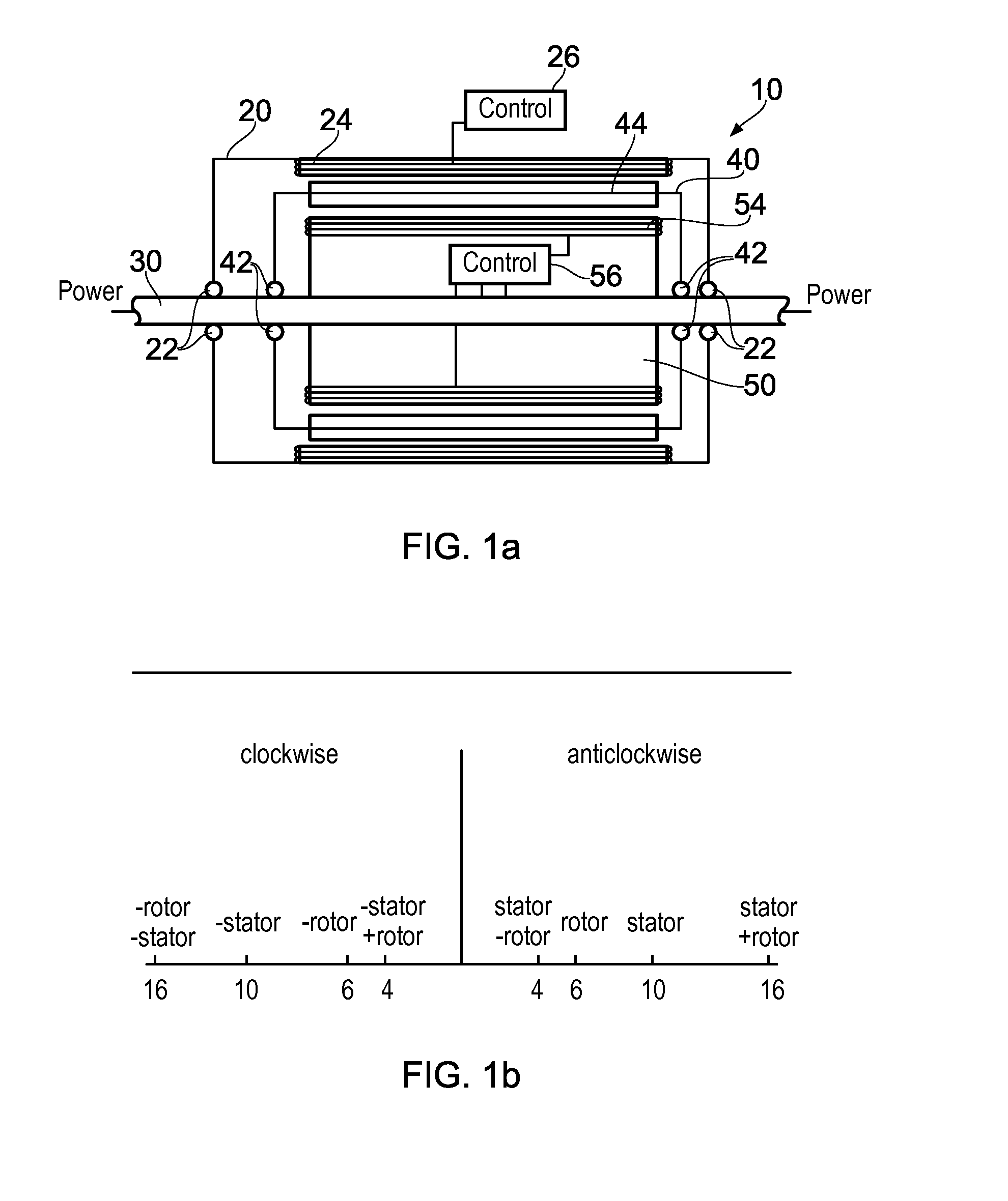
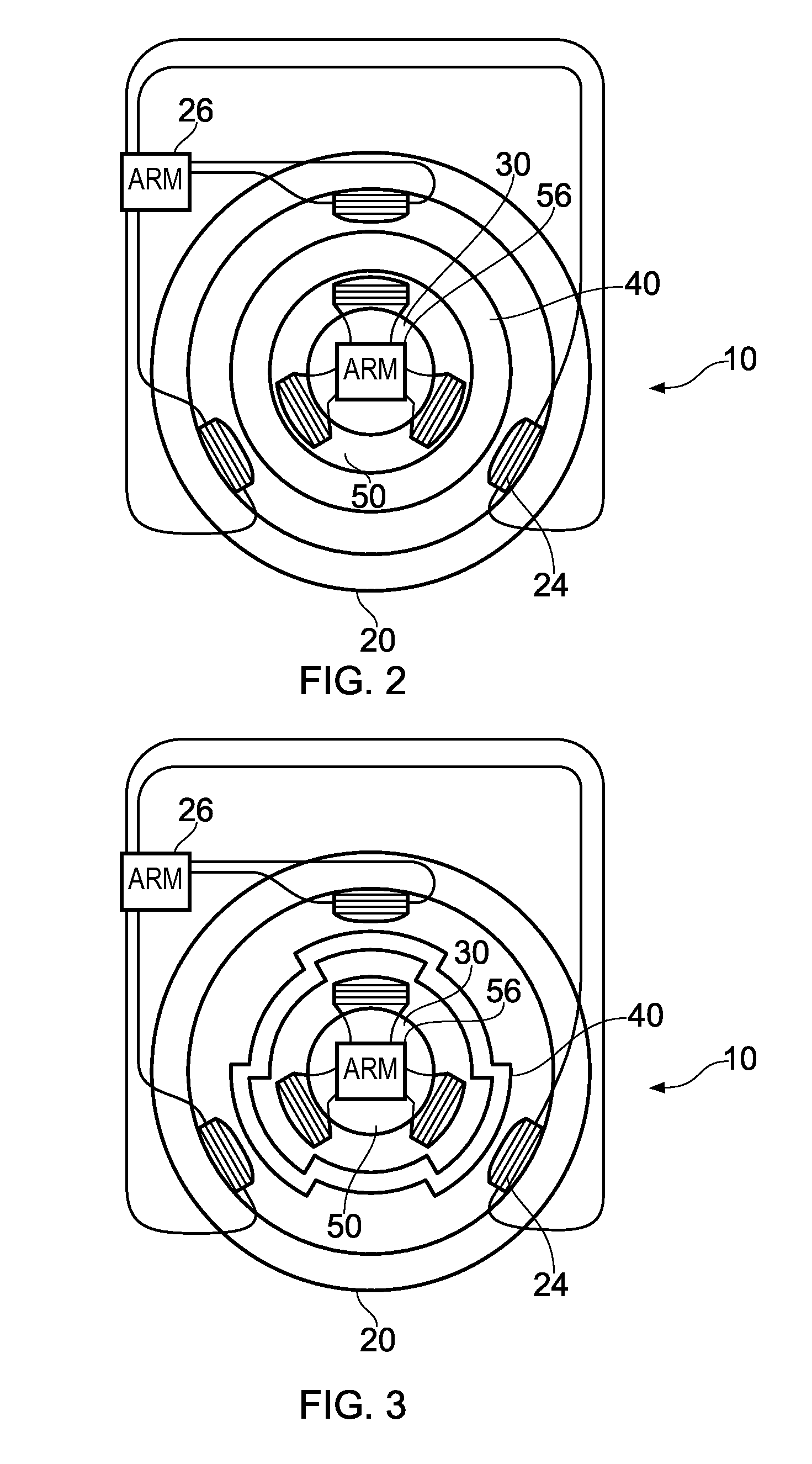
[0058]FIG. 1a shows a cross section through motor 10 according to an embodiment of the present invention. Motor 10 comprises a stator 20 mounted via bearings 22 on to rotating axle 30. There is also an intermediate screen element 40 mounted on axle 30 via bearings 42. There is then a rotating component 50 which is fixably mounted to axle 30 and rotates with it.

[0059]Stator 20 has longitudinal winding elements 24 on protrusions around its inner circumference, these windings generating a magnetic field when powered.

[0060]Rotor 50 itself has windings 54 mounted at various positions along its outer circumference on protrusions extending from the rotor and when these are powered these too generate a magnetic field. The powering of the windings 54 on rotor 50 is controlled by control circuitry 56 while the powering of the stator windings 24 are controlled by control circuitry 26.

[0061]Between the stator and the rotor there is an intermediate screening element 40. This screening element ac...


PUM


Abstract

An electric motor apparatus comprising: a stator component and a rotor component rotationally mounted coaxially with and within the stator component. The stator component and the rotor component each comprise windings configured to generate an electromagnetic field from an electric current. The electric motor further comprises an intermediate screening component rotationally mounted between the stator component and the rotor component and configured to provide at least some magnetic screening between the rotor component and the stator component. The intermediate screening component comprises at least some magnetically active sections configured such that changing magnetic fields generated by changing electric currents in the windings on either the rotor component or the stator component generate a force on the magnetically active sections causing the intermediate screening component to rotate; and control circuitry for independently controlling power supplied to the windings on the rotor component and the stator component in dependence upon a desired output rotational speed.

Description

FIELD OF THE INVENTION[0001]The technical field relates to electric motors and in particular to motors in which both the rotor component and the stator component have winding arrangements.BACKGROUND OF THE INVENTION[0002]There are several different ways of configuring electric motors each of which has its own associated advantages and disadvantages. Many of these configurations provide very efficient operations. However, this high efficiency is generally restricted to a particular optimum operating frequency of the motor and when the motor moves away from this operating frequency the efficiency may drop dramatically. In order to address this problem, motors of the prior art have been operated in conjunction with gearing systems, such that they can drive axles at different speeds, while still operating close to their own optimum rotation frequency. The provision of gears adds cost to the system and can themselves reduce efficiency.[0003]One known type of motor is the universal motor ...

Claims


Application Information

Patent Timeline
Patent Type & Authority Patents(United States)
IPC IPC(8): H02P1/46H02P25/02H02K11/00
CPCH02K11/0005H02P25/022H02K1/06H02K16/02H02K17/165H02K17/24H02K99/20H02P25/024
Inventor PIETROMONACO, DAVID
Owner ARM LTD
Why Eureka
Try Eureka