Short-range cellular booster

a cellular booster and short-range technology, applied in the field of short-range cellular boosters, can solve the problems of poor convergence, reduced link budget and cell footprint, and low information bit energy (esub>b/sub>), and achieve the effect of facilitating signal communication

Active Publication Date: 2015-09-08
NEXTIVITY INC
View PDF31 Cites 229 Cited by
  • Summary
  • Abstract
  • Description
  • Claims
  • Application Information

AI Technical Summary

Benefits of technology

[0009]In accordance with an embodiment of a communication device, a repeater mediates traffic between a network transceiver and a user transceiver in a wireless communication system. The repeater comprises a network unit that maintains a network link with the network transceiver, a user unit that maintains a user link with the user transceiver, a two-way communication pathway between the network unit and the user unit; that facilitate the communication of signals between the network transceiver and the user transceiver in autonomous repeater hops between the network transceiver and the network unit, between the user transceiver and the user unit, and between the network unit and the user unit, and a gain controller that compensates for propagation losses between the network unit and user unit alone.

Problems solved by technology

However, despite careful network design, indoor (in-building) coverage, or the coverage of places with high shadowing attenuation (e.g. tunnels) of such networks is often “patchy”, with “coverage Holes” at best, and no coverage at worst.
Although the signal may be adequate at “street-level”, it is severely attenuated by the building material, reducing the signal power in-building, resulting in the poor converges.
The problem is exacerbated in the 3rd generation systems such as Wideband Code Division Multiple Access (WCDMA) and cdma2000, as these new systems have the capability of high data transmission, which results in lower information bit energy (Eb), and much reduced link budget and cell foot-print.
Clearly all the above solutions (except the repeater solution) are very expensive and involve extensive investment in the cellular network infrastructure and are much more complex in planning and operation.
These outdoor repeaters are still too expensive for a private user, and involve careful planning.
Most use large directional antennas, or additional backhaul frequencies to reduce antenna gain specifications, which results in lower spectral efficiency and are capacity limited.
The repeaters often cause increased interference in the network, as they are outdoor devices, similar to base stations, and hence are not popular as a viable solution for providing high performance indoor coverage.
The indoor repeaters are still cheaper than the outdoor version, but typically involve installation of high directional antennas on the roof, and ensured antenna isolation, creating costly demand for skilled installation and operation.
Therefore, the system generally remains too complicated for an unskilled user and not sufficiently inexpensive for usage in a very localized coverage area.

Method used


Image

  • Short-range cellular booster
  • Short-range cellular booster
  • Short-range cellular booster

Examples


implementation example

Analogue Implementation Example

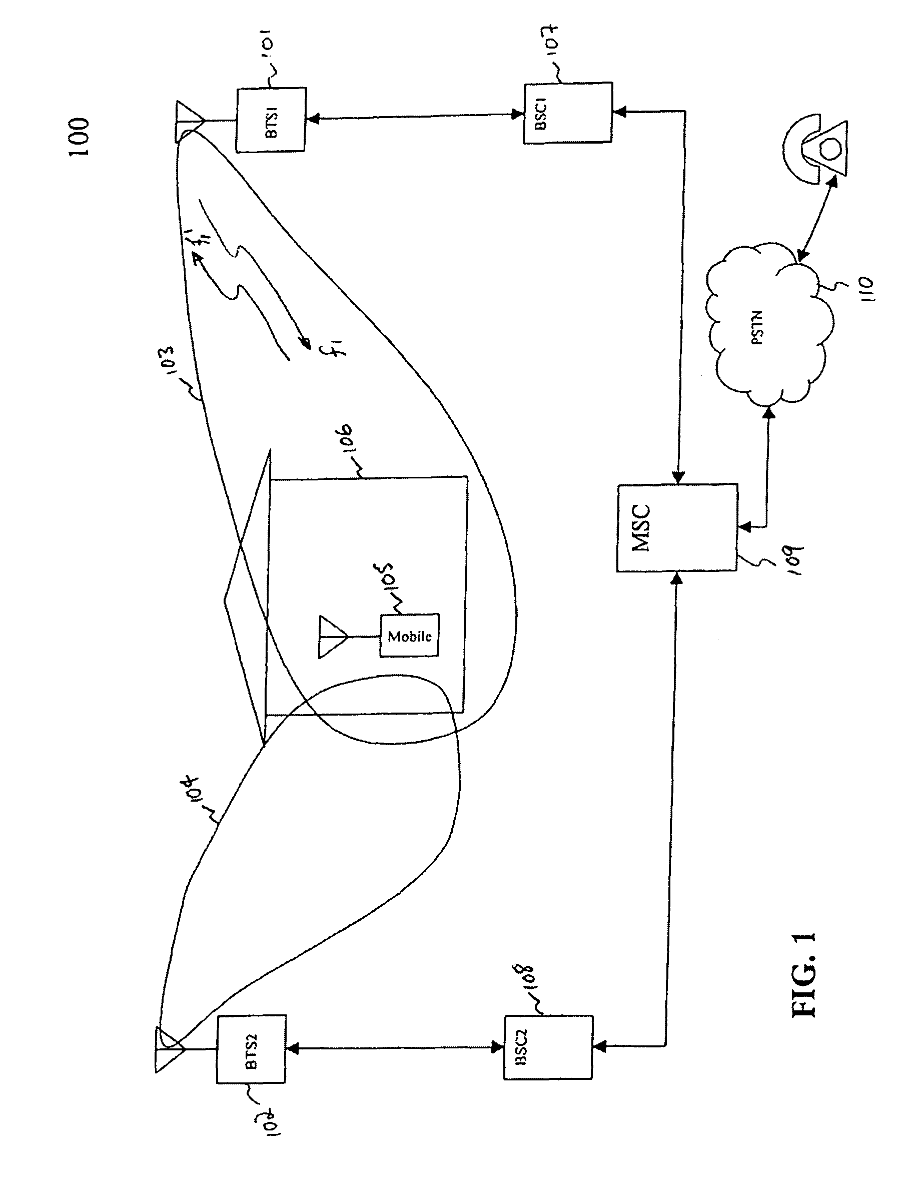
[0026]FIG. 1 shows a cellular network 100 with two base stations (BTS1 (101) & BTS2 (102)). A typical network supports more than two base stations. The disclosed system may be applied in any size network, regardless of the supported number of base stations. BTS1101 is connected to Base Station Controller BSC1107. BTS2102 is connected to Base Station Controller BSC2108. BTS2102 can also be connected to Base Station Controller BSC1107, instead of BSC2108. BSC1107 is connected to Mobile Switching Center MSC 109. BSC2108 is connected to MSC 109, or instead may be connected to another MSC in the network. MSC 109 is connected to PSTN 110. BTS1101 has an associated coverage area 103. BTS2102 has an associated coverage area 104. These coverage areas may or may not overlap. However, usually the network is planned such that there is considerable overlap, to facilitate handoffs. The mobile terminal 105 is inside building 106, in the coverage area 103 communicatin...

digital implementation example

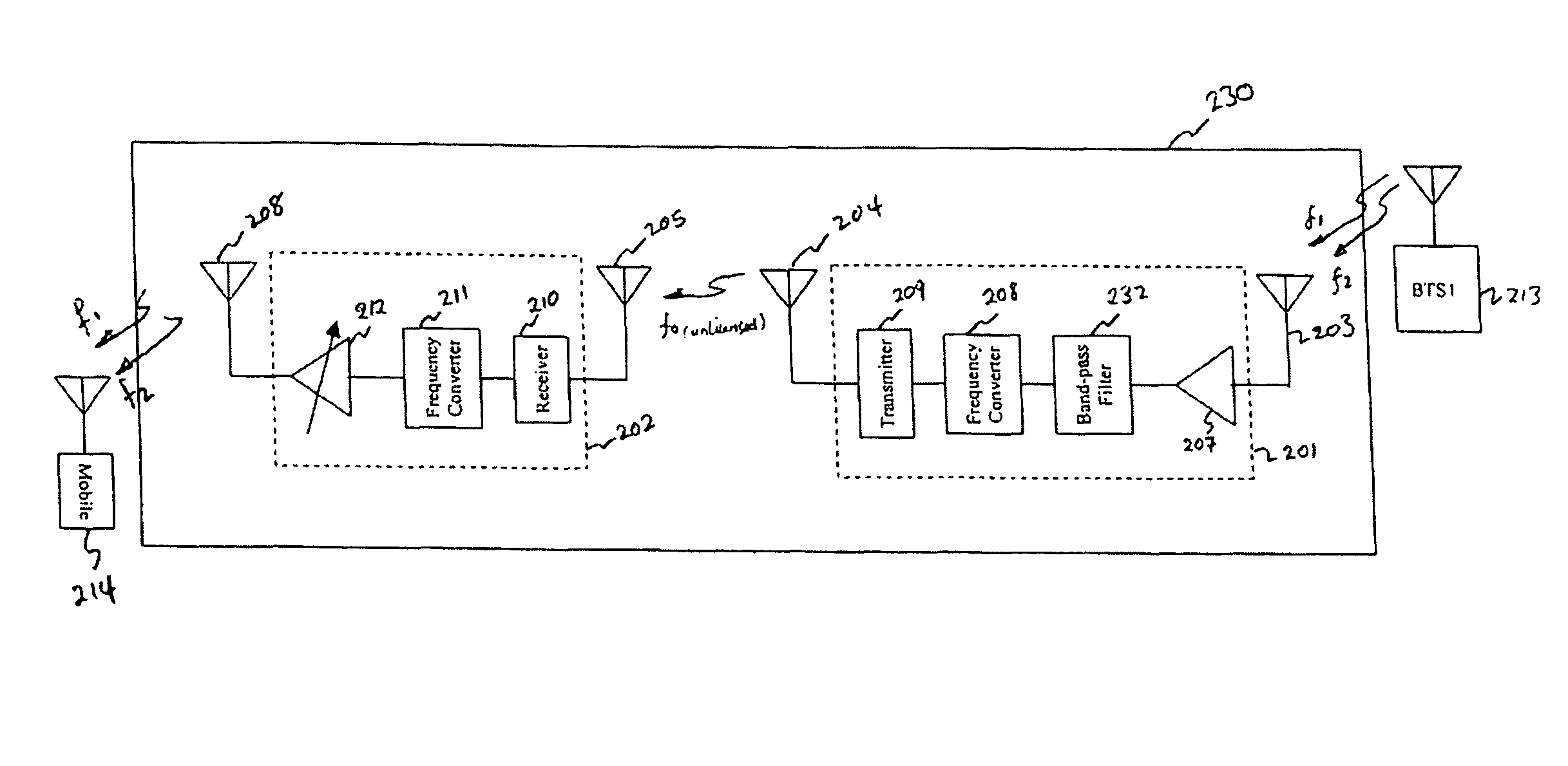
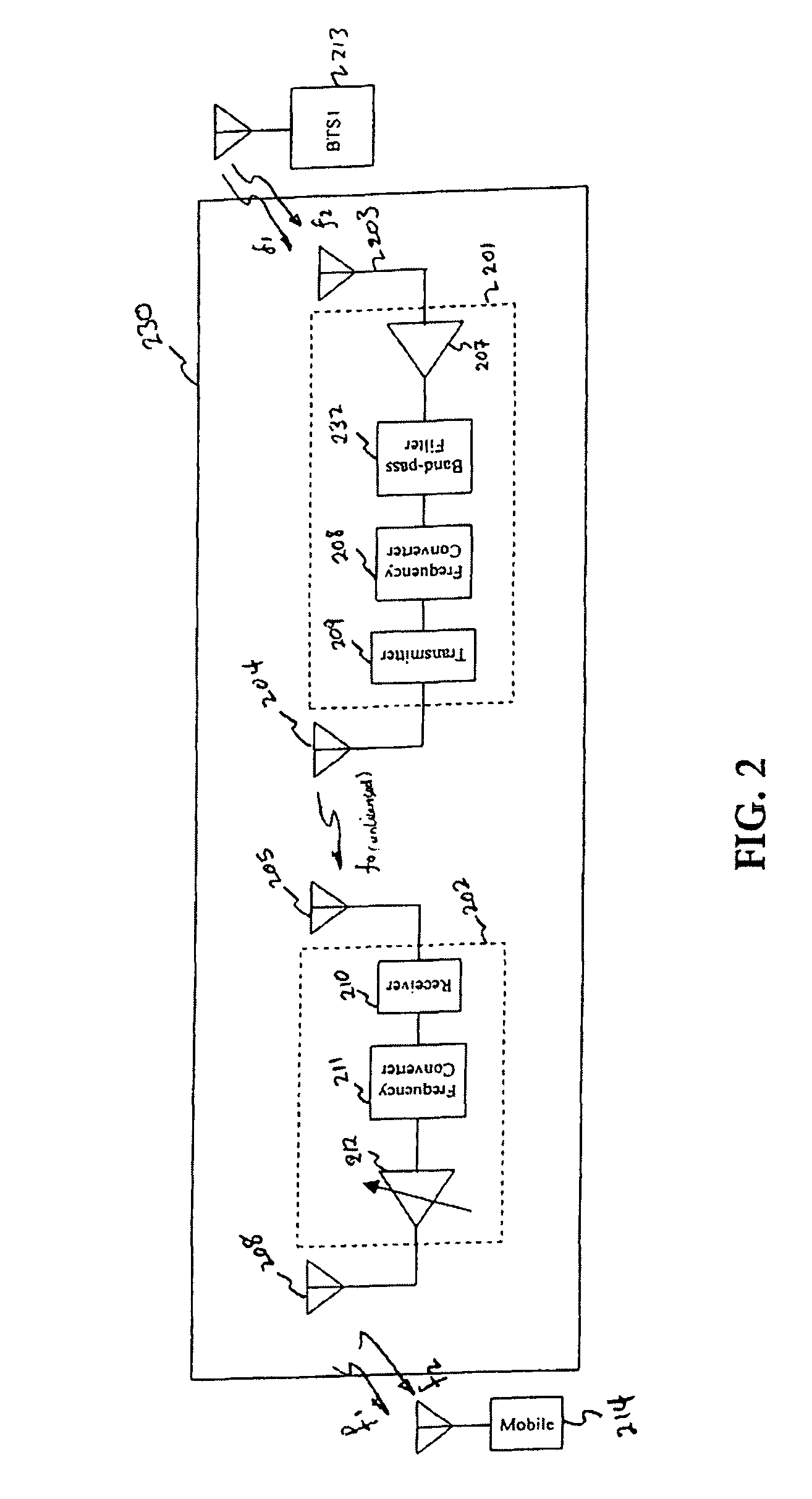
[0098]FIG. 12 shows an example of digital implementation of the Network unit 602 (labeled 1002 in FIG. 12), which is placed where good signal coverage exists, indoor or outdoors. Two antennas 1004 and 1006 are used for antenna diversity for the cellular band transmitter and receiver of the Network unit 1002. Also two antennas 1036 and 1038 are used for antenna diversity of the U-NII band operation of the Network unit 1002. Although, any diversity-combining scheme such as Maximal Ratio Combining, etc. can be used for the receiver chain, and transmit diversity schemes such as random phase change in one or both antennas for the transmitter chain, a simple scheme that is based on antenna switched diversity with “continuous switching” strategy is suggested here. The continuous switching strategy, with the switching rate selected for optimum performance (e.g. at, or twice the GSM Timeslot rate ˜4.6 msec), can be used for both transmit and receive operations, and will result in a nominal a...


PUM


Abstract

A repeater mediates traffic between a network transceiver and a user transceiver in a wireless communication system. The repeater comprises a network unit that maintains a network link with the network transceiver, a user unit that maintains a user link with the user transceiver, a two-way communication pathway between the network unit and the user unit; that facilitate the communication of signals between the network transceiver and the user transceiver in autonomous repeater hops between the network transceiver and the network unit, between the user transceiver and the user unit, and between the network unit and the user unit, and a gain controller that compensates for propagation losses between the network unit and user unit alone.

Description

CROSS REFERENCE TO RELATED APPLICATIONS[0001]This application is a national stage application, filed under 35 U.S.C. §371, of and claims priority to International Application No. PCT / US2004 / 029123, filed on Sep. 23, 2004, which in turn claims priority to U.S. Provisional Pat. App. Ser. No. 60 / 499,693, filed on Sep. 23, 2003.BACKGROUND[0002]The existing cellular networks, such as (Global System for Mobile Communications (GSM) and IS95, are intended to provide a contagious and continuous coverage, so as to support the high terminal mobility expected from such systems. However, despite careful network design, indoor (in-building) coverage, or the coverage of places with high shadowing attenuation (e.g. tunnels) of such networks is often “patchy”, with “coverage Holes” at best, and no coverage at worst. The reason for the impaired indoor coverage is that the cellular base stations are usually placed outside buildings, higher than the average building heights, to provide large area cover...

Claims


Application Information

Patent Timeline
Patent Type & Authority Patents(United States)
IPC IPC(8): H04B7/15H04B7/155H04BH04B17/40
CPCH04B7/15542H04B7/15535H04B7/15585H04B7/15564H04B7/2606H04B7/155H04B17/40
Inventor MOHEBBI, BEHZAD
Owner NEXTIVITY INC
Why Eureka
Try Eureka