
System and method for demand driven network topology management

a topology management and demand technology, applied in the direction of vehicle position/course/altitude control, process and machine control, instruments, etc., can solve the problems of complex coordination task of landing the aircraft, unworkable, unexpected events, etc., to facilitate network communication, facilitate network operation, and facilitate network communication.

Active Publication Date: 2015-09-08
THE BOEING CO
View PDF21 Cites 19 Cited by
  • Summary
  • Abstract
  • Description
  • Claims
  • Application Information

AI Technical Summary

Benefits of technology

The patent describes a network where nodes can be moved to change the coverage and make better use of resources. The movement of nodes can be continuous or occasional to adjust network coverage. The network also has links that can be established, broken, and re-established to improve efficiency. This allows for flexible and efficient use of network resources.

Problems solved by technology

The coordination task of landing the aircraft is complex.
Furthermore, unexpected events may occur, such as a runway being closed, that would involve altering the original plan.
Specifying fixed distances may be difficult or unworkable in light of competing constraints.
In such a case, ordinarily a higher control priority would be assigned to the network constraint because the network constraint guarantees communication at all times. During conflicting scenarios, higher priority fields leave too few degrees of freedom available for the full execution of low priority fields, and the low priority fields are considered only partially feasible.
Further, some aircraft, as a result of the design of the aircraft, result in more surrounding turbulence than other aircraft of the same or larger size.
With a large group of agents, it may not be possible to continually update other agents with status information.
For example, the movement of the fifth node 2250 in the direction of 2430 may be determined not to improve the communications capabilities of the system of nodes and, in fact, may decrease performance such that movement in the direction of 2430 is not considered by the methodology.
However, any further movement in such direction was found to be less beneficial so the movement ended at 2422.
However, any further movement was found to either not improve performance or to decrease performance such that the termination point is at 2454.

Method used


Image

  • System and method for demand driven network topology management
  • System and method for demand driven network topology management
  • System and method for demand driven network topology management

Examples


Embodiment Construction

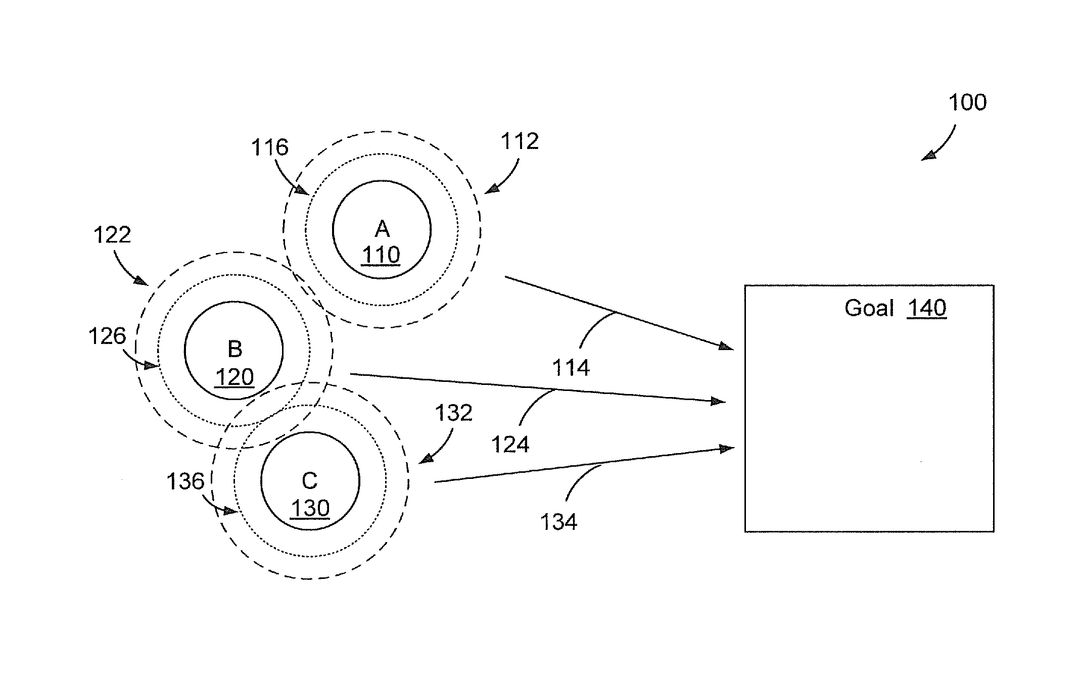
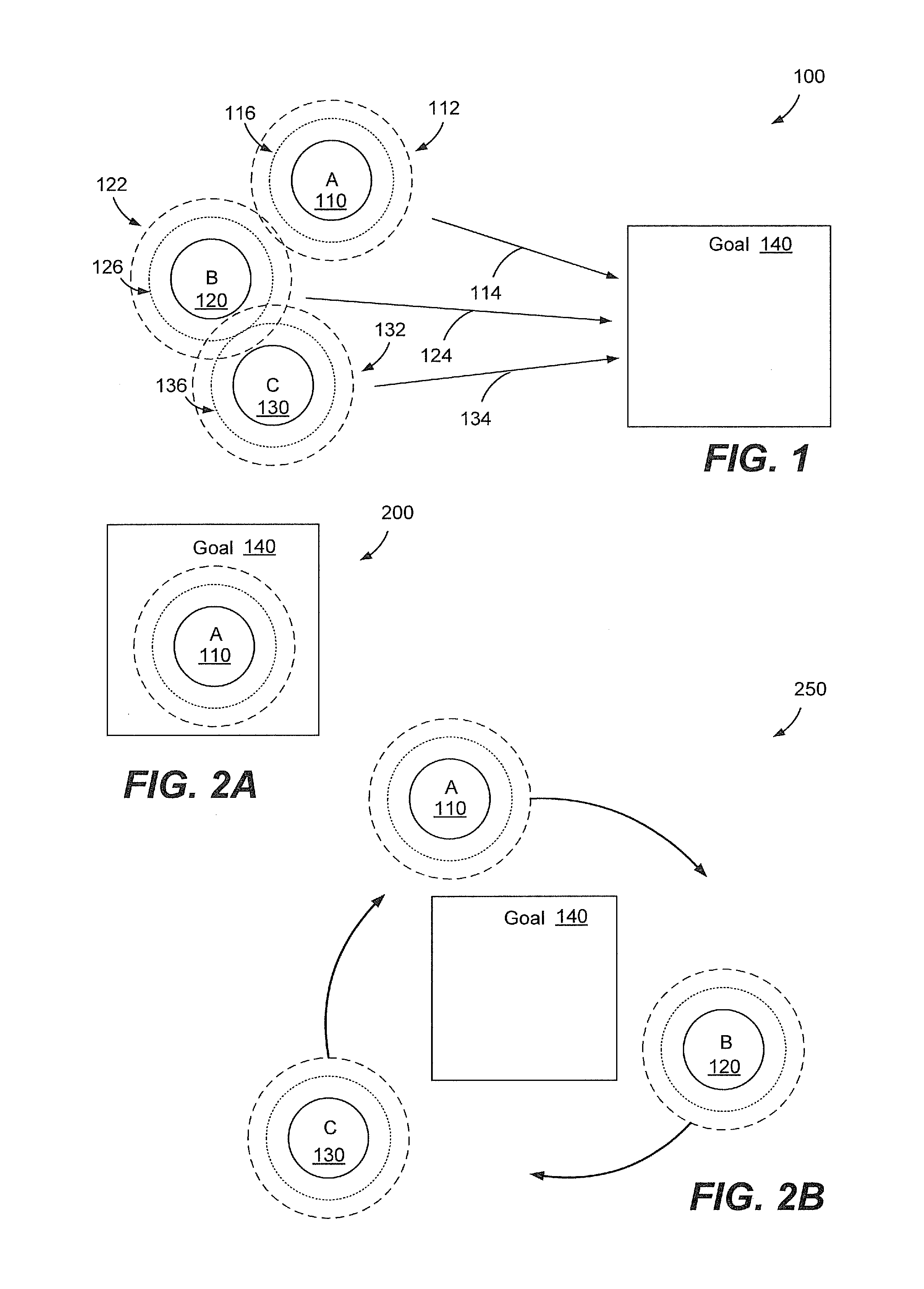
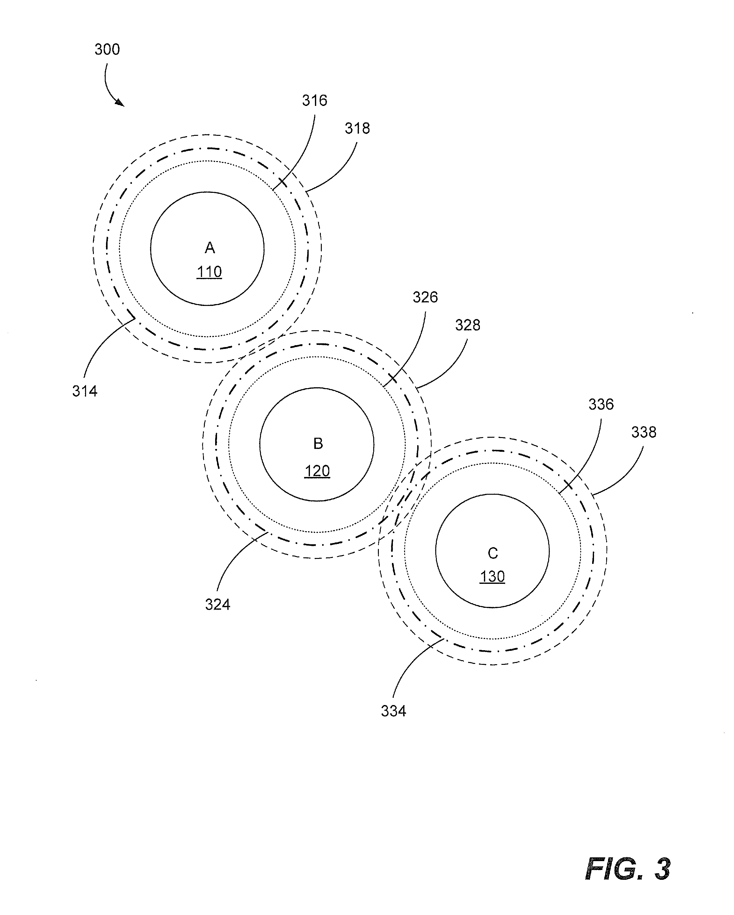
[0041]According to illustrative embodiments of the present disclosure, a plurality of agents or nodes participating in a shared operation may be cooperatively moved or placed so as to satisfy specified constraints through the use of potential field methods. Potential field methods are used to model physical / virtual gravitational or magnetic fields by depicting how an object is affected by a plurality of forces to which the object is subjected. Potential fields may be created to model desired forces imputed to the nodes. For example, instead of using a potential field to model a magnetic force between two nodes, a potential field may be used to model a desired repulsion and a desired attraction to maintain the two nodes at a desirable communication distance where the nodes are neither too close together as to cause communication interference nor too far apart so that the nodes are beyond communication range of each other. By applying potential fields to model various constraints, suc...


PUM


Abstract

Methods, systems, and devices are disclosed to facilitate operation of a network. First network state data descriptive of a first network state is received. The first network data includes network demand associated with nodes of a dynamic network, where the nodes of the dynamic network include at least one movable node. The first network data also includes a node state of each node of the dynamic network. At least one first link is automatically established between two or more nodes of the dynamic network to satisfy at least a portion of the network demand. Link data is generated where the link data is descriptive of node utilization, the at least one first link, and assignment of the portion of the network demand to the at least one first link. One or more changes to the dynamic network are modeled based on the link data to identify a second network state, wherein the second network state satisfies a greater quantity of the network demand than the first network state.

Description

RELATED CASE[0001]The present application is a continuation-in-part of previously-filed U.S. patent application Ser. No. 12 / 494,089 for “APPLICATION OF POTENTIAL FIELD METHODS IN DIRECTING AGENTS,” filed on Jun. 29, 2009. The present application claims the filing date and priority of the previously-filed application.FIELD OF THE DISCLOSURE[0002]The present disclosure is generally related to demand-driven positioning of nodes and establishing of links in network topology management.BACKGROUND[0003]Agents or nodes that participate in performance of a task, whether the agents or nodes are autonomous devices or human-controlled devices relying on automated control systems, may seek to dynamically coordinate their movements and positions to aid in the collective performance of the task. There are myriad examples of systems in which agents manually coordinate their movements to act in harmony with a group of similarly-situated agents. To take just one example, in landing at commercial air...

Claims


Application Information

Patent Timeline
Patent Type & Authority Patents(United States)
IPC IPC(8): H04W84/18H04W24/02H04W84/06H04W84/20G05D1/10H04W16/00
CPCH04W84/06H04W84/20G05D2201/0207G05D1/104H04W16/00H04W24/02
Inventor AYYAGARI, ARUNLI, WINFENGBATTLES, CRAIG F.DORSETT, MICHAEL A.
Owner THE BOEING CO
Learn More