
Method and apparatus for measuring injection energy of organic light emitting diode display

a technology of light emitting diodes and injection energy, which is applied in the direction of voltage-current phase angles, instruments, semiconductor lamp usage, etc., can solve the problems of difficult to accurately predict the luminous efficiency and life-span of organic light emitting diodes, and difficult to measure injection energy (activation energy) of organic emission layers, etc., to achieve optimal life-span and optimal luminous efficiency

Inactive Publication Date: 2015-09-08
SAMSUNG DISPLAY CO LTD
View PDF23 Cites 0 Cited by
  • Summary
  • Abstract
  • Description
  • Claims
  • Application Information

AI Technical Summary

Benefits of technology

The patent text describes a method for selecting suitable voltage values for an organic light emitting diode display device based on the relationship between voltage values and injection energy values. This helps to achieve optimal luminous efficiency and life-span.

Problems solved by technology

Nevertheless, it may be difficult to measure injection energy (activation energy) of the organic emission layer.
As a result, it may be difficult to correctly predict the luminous efficiency and the life-span of the organic light emitting diode (OLED) display.

Method used


Image

  • Method and apparatus for measuring injection energy of organic light emitting diode display
  • Method and apparatus for measuring injection energy of organic light emitting diode display
  • Method and apparatus for measuring injection energy of organic light emitting diode display

Examples


Embodiment Construction

[0038]Embodiments of the invention are described more fully hereinafter with reference to the accompanying drawings. As those skilled in the art would realize, the described embodiments may be modified in various ways, all without departing from the spirit or scope of the present invention.

[0039]The drawings and description are to be regarded as illustrative in nature and not restrictive. Like reference numerals may designate like elements throughout the specification.

[0040]Sizes and thicknesses of constituent members shown in the accompanying drawings are for better understanding and / or for ease of description. Embodiments of the present invention are not limited to the illustrated sizes and thicknesses.

[0041]Various embodiments are described herein below, including methods and techniques. Embodiments of the invention might also cover an article of manufacture that includes a non-transitory computer readable medium on which computer-readable instructions for carrying out embodiment...


PUM


Abstract

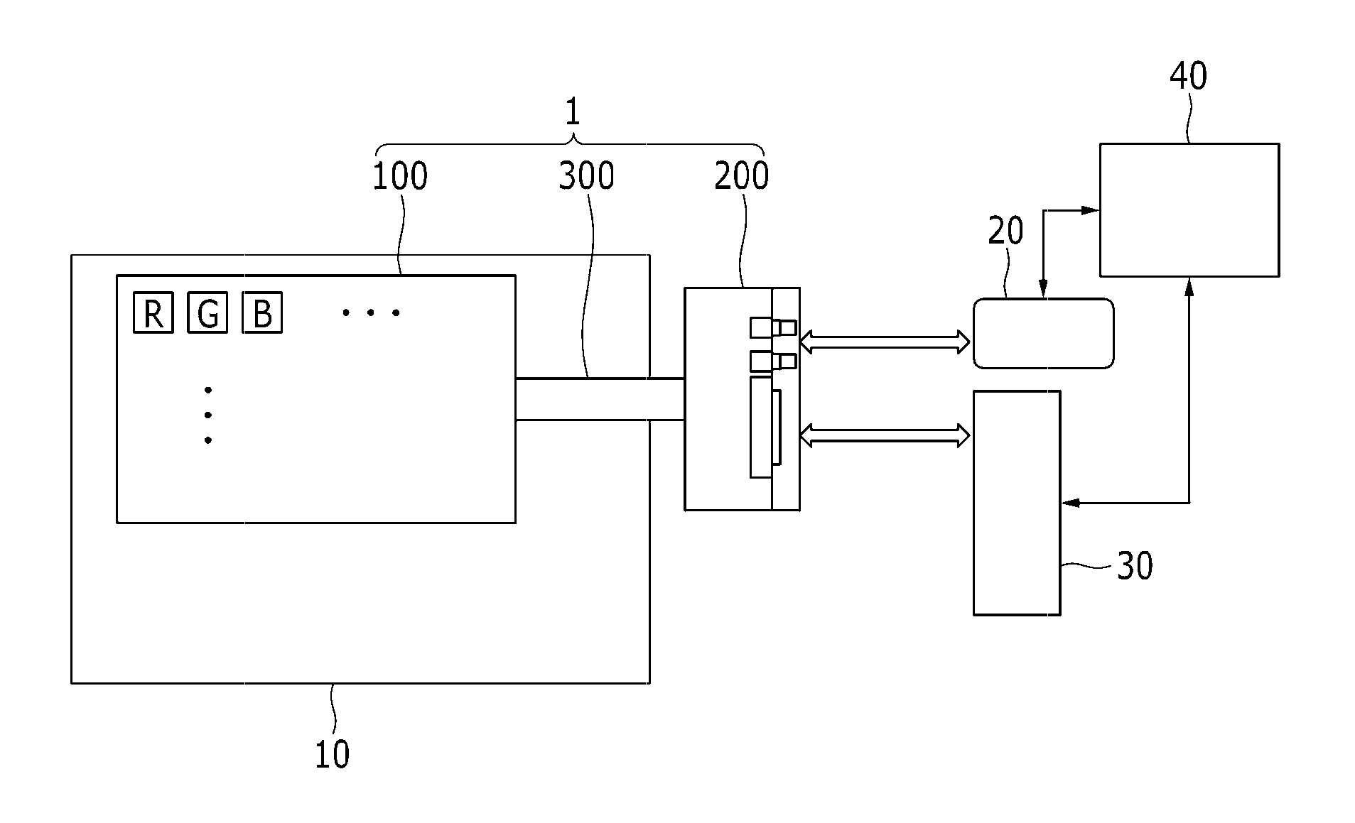
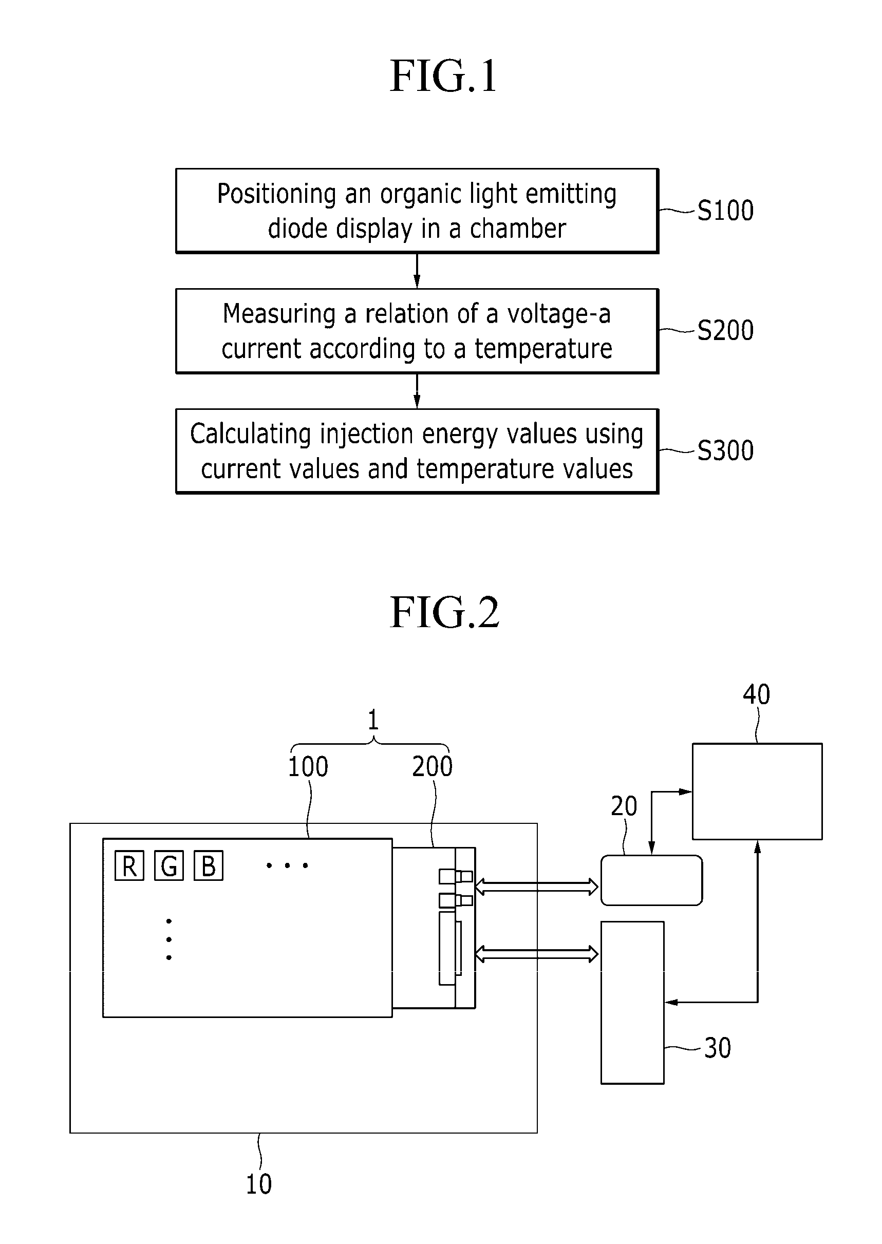
A method is used for measuring injection energy associated with an organic light emitting diode display device. The method includes disposing the display panel inside a chamber and controlling temperature inside the chamber. The method further includes determining a plurality of electric current values corresponding to a plurality of temperature values for each voltage value of plurality of voltage values, the plurality of voltage values being associated with voltages provided to the organic light emitting member. The method further includes calculating a plurality of injection energy values using the plurality of electric current values and the plurality of temperature values.

Description

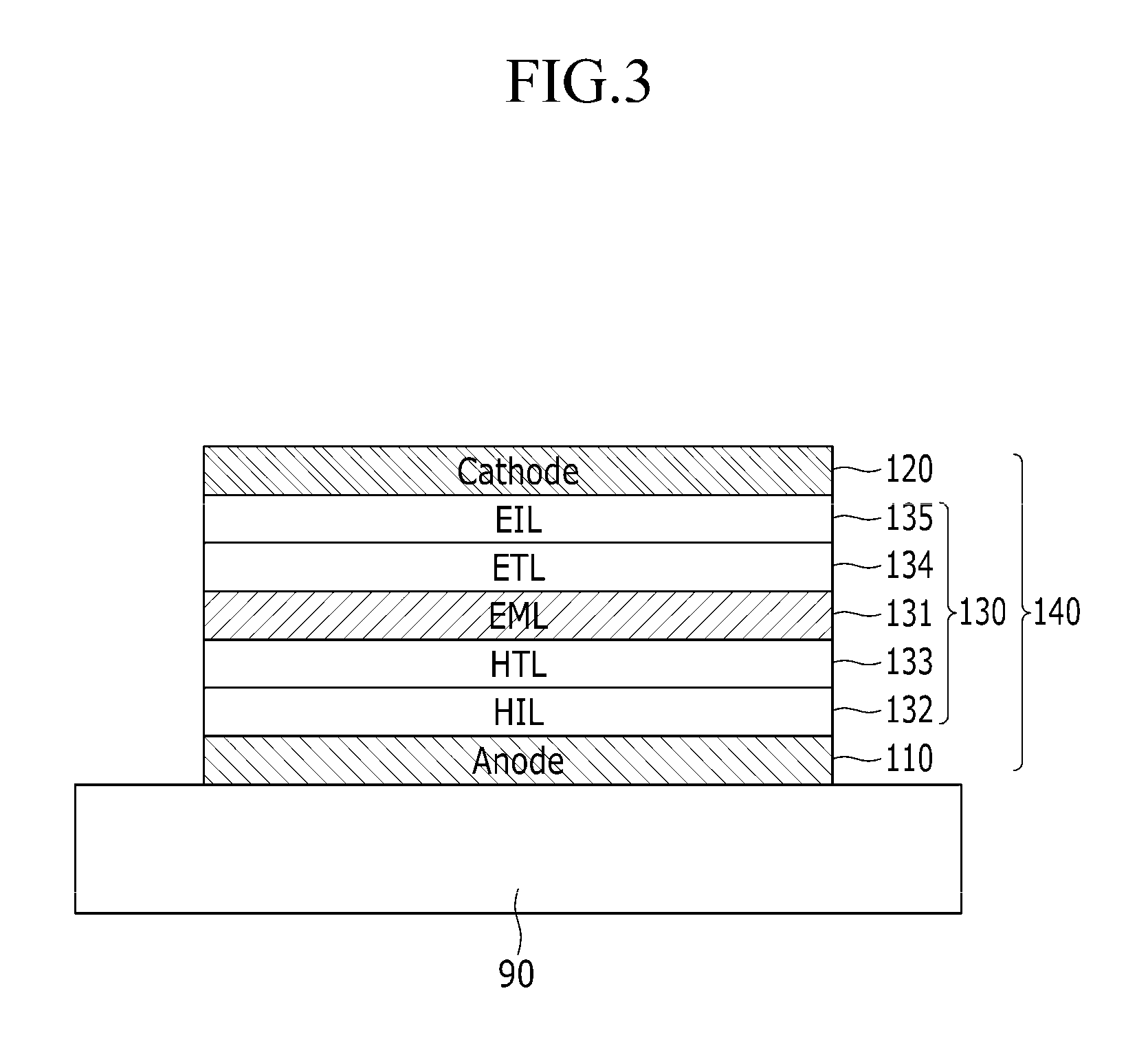
CROSS-REFERENCE TO RELATED APPLICATION[0001]This application claims priority to and the benefit of Korean Patent Application No. 10-2013-0049437 filed in the Korean Intellectual Property Office on May 2, 2013, the entire contents of which are incorporated herein by reference.BACKGROUND[0002]1. Field[0003]The present invention is related to a method and an apparatus for measuring injection energy of an organic light emitting diode (OLED) display.[0004]2. Description of the Related Art[0005]An organic light emitting diode (OLED) display typically includes a cathode, an anode, and an organic emission layer interposed between the cathode and anode. Electrons injected from the cathode and holes injected from the anode may be bonded to each other in the organic emission layer to form excitons, and light may be emitted while the excitons discharge energy. Injection energy of organic light emitting diode (OLED) display is energy associated with the injected electrons and the injected holes....

Claims


Application Information

Patent Timeline
Patent Type & Authority Patents(United States)
IPC IPC(8): G01R25/00H05B33/08H05B44/00
CPCH05B33/0896H05B45/60Y02B20/30H05B33/10H10K71/00
Inventor SHIM, TAE-KYUSHIN, HYE-LIMSONG, WON-JUNKIM, JAE-BOK
Owner SAMSUNG DISPLAY CO LTD
Learn More