Device and method for cooktop fire mitigation

a technology for fire mitigation and cooktops, applied in the field of devices and methods for cooking stoves, can solve the problems of insufficient fire risk indicator, insufficient time to catch high pan temperatures, and significant source of property damage and injury in residential cooking fires, and achieve the effect of reducing the risk of cooking fires

Active Publication Date: 2015-09-15
PRIMAIRA
View PDF26 Cites 37 Cited by
  • Summary
  • Abstract
  • Description
  • Claims
  • Application Information

AI Technical Summary

Benefits of technology

[0009]The present invention generally relates to the field of cooktops and ranges (defined as an integrated cooktop and oven). As used herein, the term “cooktop” refers generally to all kinds of cooking appliances that use a gas burner and / or an electric element for heating or cooking a food material, such as cooktops, ranges and cooking hobs. This invention provides a device and method for mitigating the risk of cooktop fires with the use of a cookware-temperature limiting control to prevent food ignition in a pan on the cooktop. It is another intention of this invention to provide a device and method that takes automatic corrective actions to prevent food ignition and subsequent fire. It is another intention of this invention to provide a device and method that differentiate between standard cooking practices and conditions that may lead to ignition of food in the pan, so that the automatic corrective actions do not interfere with otherwise safe cooking practices.
[0015]There is access for a pan-bottom temperature sensor according to this invention to contact the pan directly. There is some thermal inertia in the electric element. The implication of the thermal inertia of the coil is that the pan temperature can continue to rise even after the power to the element has been reduced or removed. Therefore, even with a sensor contacting the pan directly, there is a need to know both the temperature of the pan and its rate of change of temperature in order to ensure that the temperature does not exceed a preset value. When a rate of change of the pan temperature is quite low, the measured pan temperature can be allowed to approach the threshold temperature more closely, without risk of temperature overshoot.
[0016]In one embodiment of this invention, the set points of a control algorithm (the control logic) are defined and used to prevent vessel temperatures from rising above, for example, roughly 700° F. without interfering with normal cooking. The control algorithm of one embodiment of this invention uses a combination of rate of change and threshold monitoring to determine when to interrupt the element's power. This combination of threshold temperature and rate of change allows the control device to avoid overshoot of pan temperature that may occur during an initial heat-up phase of cooking, while maintaining a high enough steady state temperature threshold for excellent cooking performance.
[0019]With a gas cooktop, the pan is placed on a grate that is located above the gas burner. The heat from the flame is transferred into the pan primarily by convection. As is the case with the electric coil, there is access for a pan-bottom temperature sensor to contact the pan directly. There is some thermal inertia in the gas, but it is less than that of the electric coil. The rapid responsiveness of the gas burner makes it possible to reduce pan temperature by turning the flame down rather than turn it off entirely. The turndown approach significantly simplifies the process of returning the heat to the previous input rate.

Problems solved by technology

Residential cooking fires remain a significant source of property damage and injury.
Time is not a sufficient indicator of fire risk as the time to reach the ignition temperature can vary with element power, pan size and type, oil amount, etc.
This is not sufficient to catch high pan temperatures when the hob is at its standard, maximum level.
U.S. Pat. No. 6,663,009 to Bedetti describes a configuration of sensors around a gas flame to detect pan temperature and control heat output of the burner, but does not identify an algorithm that would be able to mitigate a safety problem from this temperature sensor input.

Method used


Image

  • Device and method for cooktop fire mitigation
  • Device and method for cooktop fire mitigation
  • Device and method for cooktop fire mitigation

Examples


Embodiment Construction

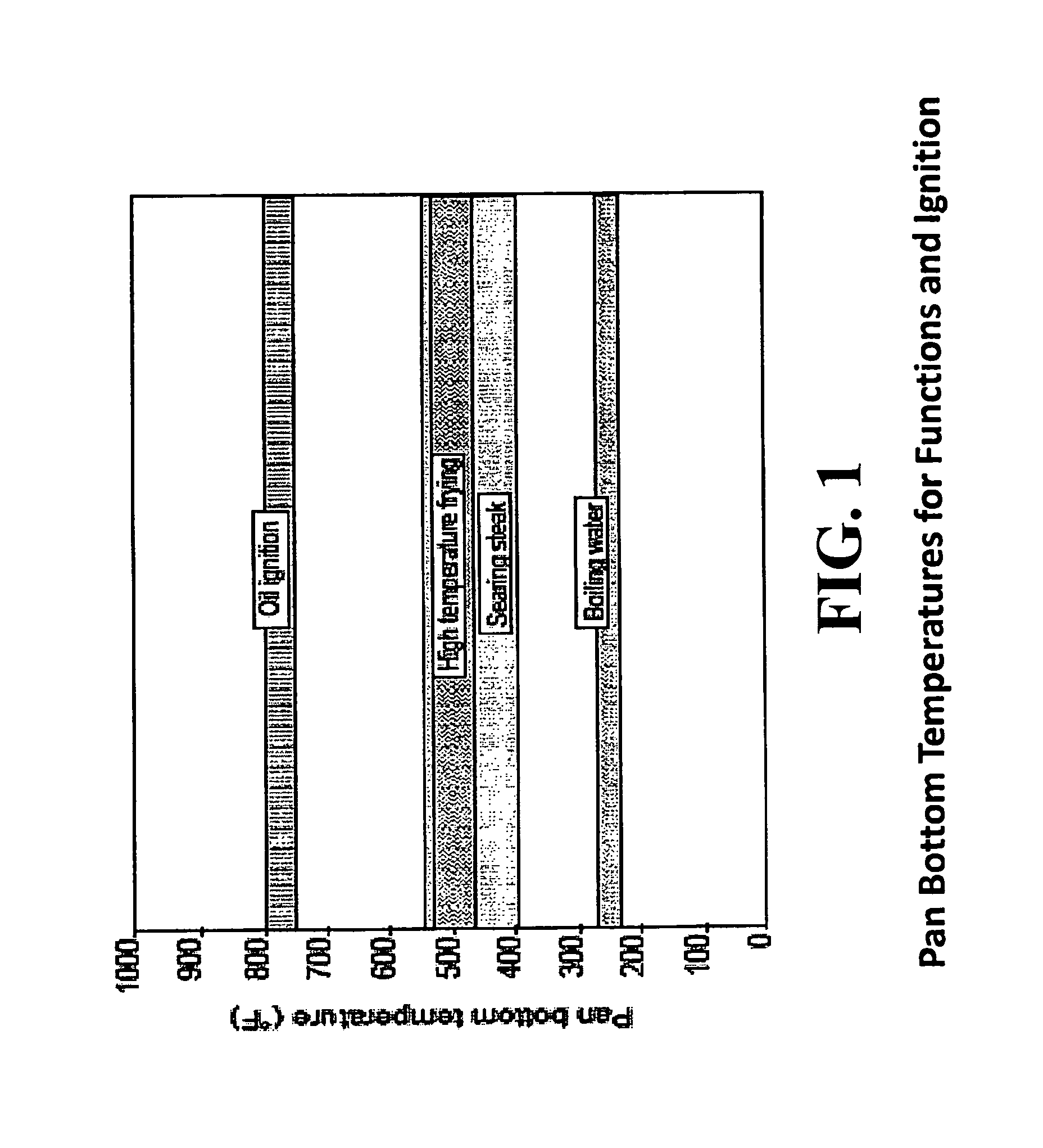
[0040]The present invention provides a temperature-dependent cooktop safety device and method for various cooktops, such as including a gas burner or electric element for heating food material in a cookware container, referred to generally herein as a “pan.”FIG. 1 illustrates approximate pan bottom temperatures of various cooking functions, along with an approximate temperature threshold above which oil in the pan could ignite. The invention includes a temperature detection means for detecting or inferring the temperature of the bottom face of the pan and automatically reducing the pan temperature to avoid the ignition situation. The invention includes a control device, or controller for short, that monitors a temperature sensor, and includes a heat control circuit for controlling the amount of heat issued from the electric heating element or gas burner, based upon an algorithm that defines the on / off state based upon characteristics of the detected temperature.

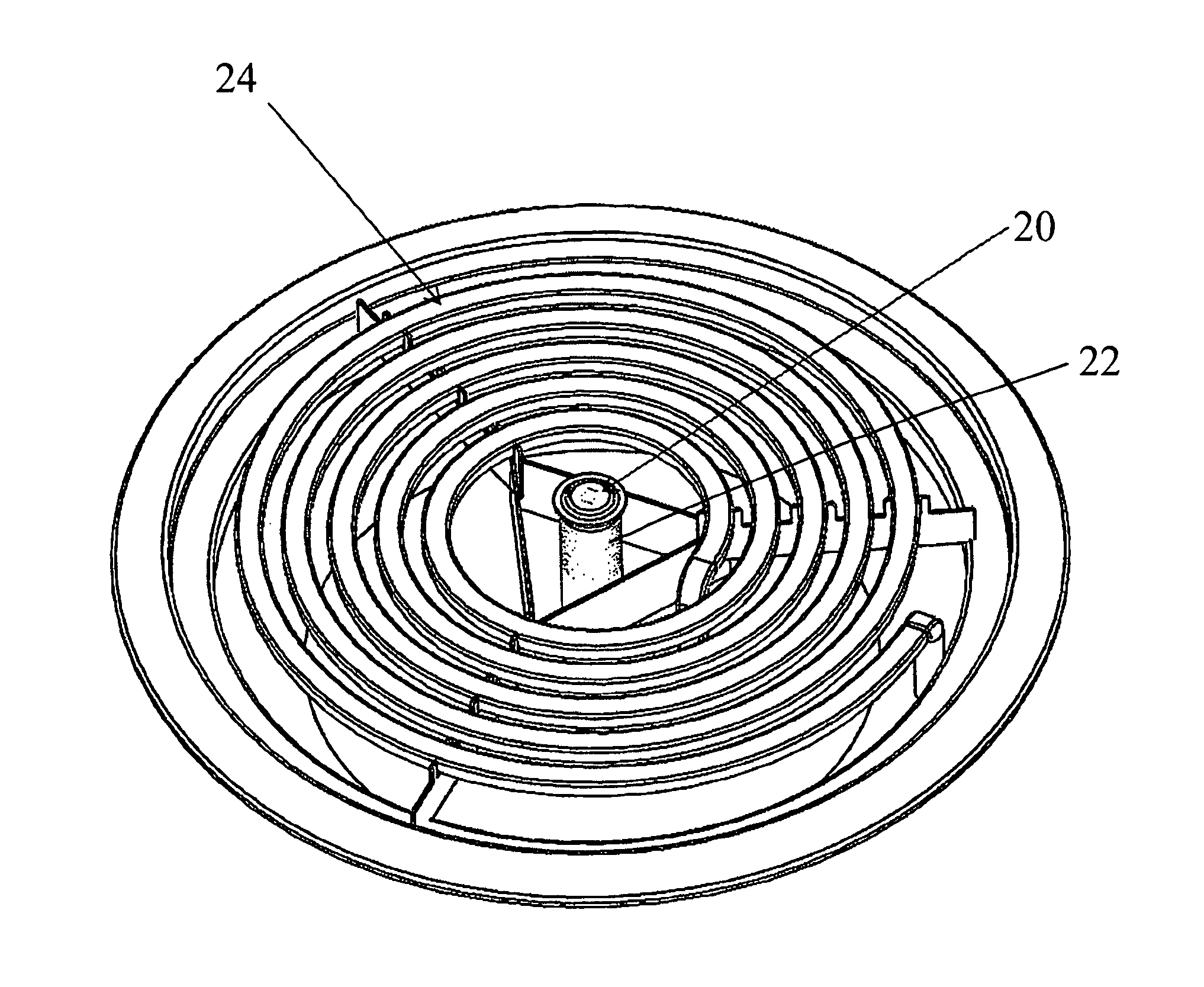
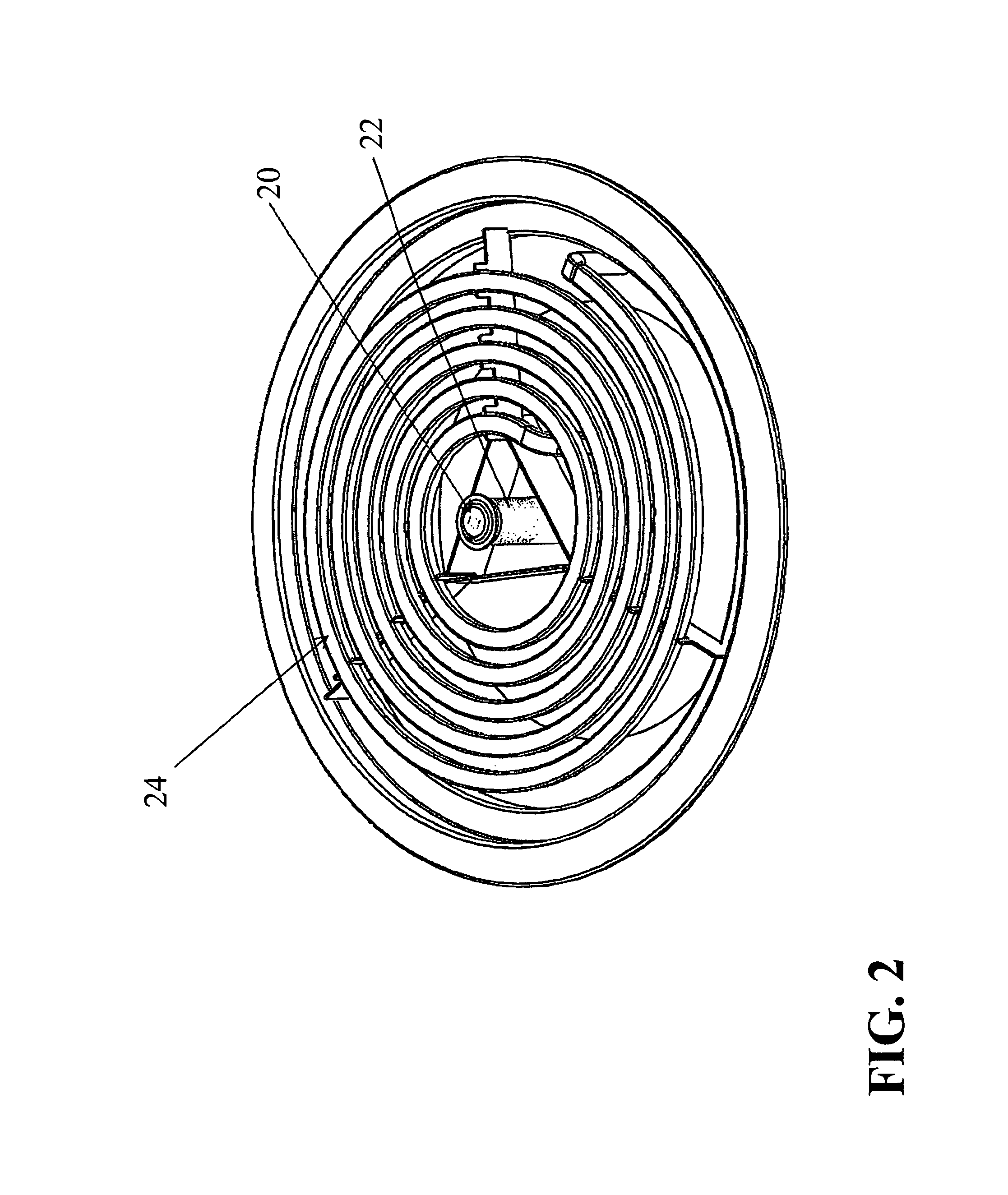
[0041]FIG. 2 shows a ...


PUM


Abstract

A device for limiting the temperature of cookware on a cooktop to a threshold level that corresponds to an oil ignition temperature. The device includes a temperature sensor that is positioned adjacent a bottom of the cookware on the cooktop. A control device in combination with each of the temperature sensor and the cooktop monitors the temperature and adjusts a heating element of the cooktop as needed to avoid cooking oil ignition. The temperature sensor can be a spring loaded temperature sensor to ensure and / or absorb contact with the cookware.

Description

CROSS REFERENCE TO RELATED APPLICATION[0001]This Patent Application claims the benefit of U.S. Provisional Application, Ser. No. 61 / 683,097, filed on 14 Aug. 2012. The co-pending Provisional Patent Application is hereby incorporated by reference herein in its entirety and is made a part hereof, including but not limited to those portions which specifically appear hereinafter.BACKGROUND OF THE INVENTION[0002]Residential cooking fires remain a significant source of property damage and injury. According to Consumer Product Safety Commission (CPSC) staff estimates, all cooking equipment-related fires account for nearly 40% of all residential fires that were attended to by a fire department while range / oven, non-confined fires account for approximately 14,600 incidents per year (D. Miller and R. Chowdhury; 2006-2008 Residential Fire Loss Estimates; U.S. Consumer Product Safety Commission, 2011). Government funded research has demonstrated that food and pan-bottom temperatures are reliabl...

Claims


Application Information

Patent Timeline
Patent Type & Authority Patents(United States)
IPC IPC(8): F24H1/18A47J27/00A47J27/62A62C3/00
CPCA62C3/006A47J27/62F24C3/126F24C7/083F24C7/087F24C3/122F24C7/088H05B3/22H05B3/746H05B3/76
Inventor LUONGO, WADEBENEDEK, KARENCARBONE, PHILIP C.
Owner PRIMAIRA
Why Eureka
Try Eureka