
Flexible display device and method of manufacturing the same

a flexible display and display device technology, applied in sustainable manufacturing/processing, identification means, instruments, etc., can solve the problems of deterioration of image quality, increased weight due to metal substrate, increased thickness of flexible display devices, etc., to prevent flexibility deterioration and block external noise from affecting image quality

Active Publication Date: 2015-09-15
LG DISPLAY CO LTD
View PDF8 Cites 2 Cited by
  • Summary
  • Abstract
  • Description
  • Claims
  • Application Information

AI Technical Summary

Benefits of technology

[0016]An object of the present invention is to provide a flexible display device that includes an insulating substrate and does not include a conductive film to prevent flexibility deterioration and is capable of blocking influence of external noise on image quality, and a method of manufacturing the same.

Problems solved by technology

However, as a substrate formed of a soft material is flexible, careful attention is required to perform deposition of thin films, patterning, and the like to form a cell array and a light emitting structure thereon with a process error less than a critical point.
Meanwhile, since flat display devices such as flexible display devices including a cell array and a light emitting structure including thin films, image quality may be deteriorated due to external noise.
In this case, a process of connecting the metal substrate to the external ground voltage source is further required after attachment of the metal substrate, and the flexible display device has increased thickness, decreased flexibility, and increased weight due to the metal substrate.
In addition, since the metal substrate is reflective, it is not possible to perform foreign matter detection for a cell array and a light emitting array outside the metal substrate.
As a result, manufacturing time and manufacturing costs are increased.

Method used


Image

  • Flexible display device and method of manufacturing the same
  • Flexible display device and method of manufacturing the same
  • Flexible display device and method of manufacturing the same

Examples


Embodiment Construction

[0031]Reference will now be made in detail to the preferred embodiments of the present invention, examples of which are illustrated in the accompanying drawings. Wherever possible, the same reference numbers will be used throughout the drawings to refer to the same or like parts.

[0032]A flexible display device according to an embodiment of the present invention and a method of manufacturing the same will be described in detail.

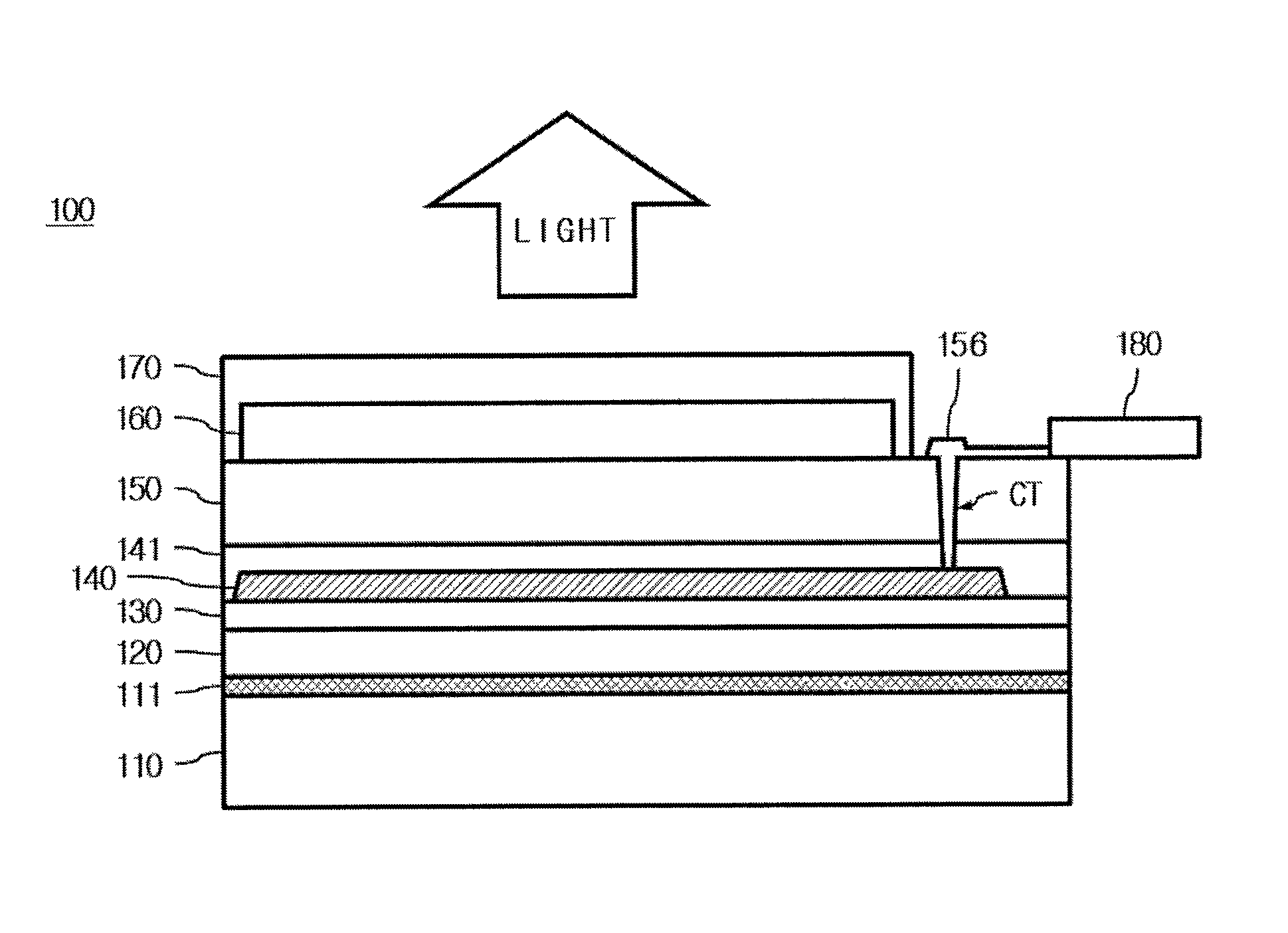
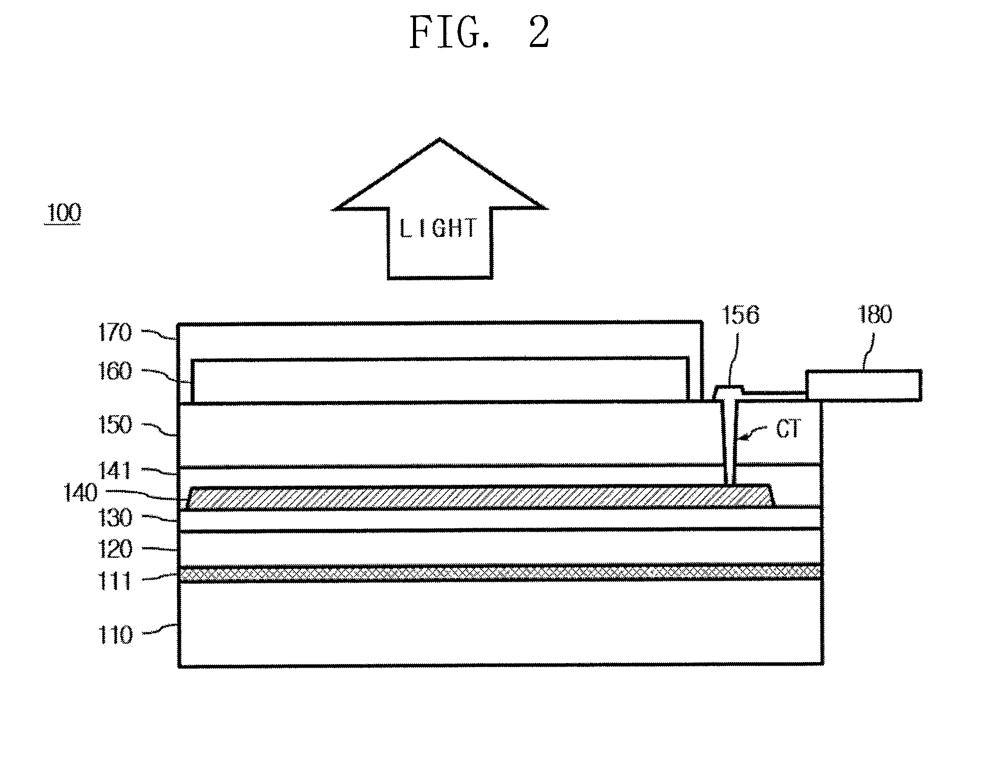
[0033]First, a flexible display device according to an embodiment of the present invention will be described with reference to FIGS. 2 to 4.

[0034]FIG. 2 is a cross-sectional view illustrating a flexible display device according to an embodiment of the present invention. FIG. 3 is a cross-sectional view illustrating a flexible display device according to another embodiment of the present invention. FIG. 4 is a cross-sectional view of an example of a cell array and a light emitting array of FIGS. 2 and 3.

[0035]As illustrated in FIG. 2, the flexible display devic...


PUM


Abstract

A flexible display device is discussed. The flexible display device according to an embodiment includes an insulating and flexible substrate on which an adhesive layer is formed, a support layer adhered to the substrate via the adhesive layer, a cell array formed above the support layer, defining a plurality of pixel regions, and including a ground line connected to a ground voltage source of an external circuit, a light emitting array including a plurality of light emitting structures formed on the cell array, a sealing layer formed on the cell array, and a buffer layer, a shielding layer, and a bottom insulating layer formed between the support layer and the cell array. The light emitting array emits light toward the sealing layer, and the ground line is connected to the shielding layer through a contact hole to partially expose the shielding layer.

Description

[0001]This application claims the benefit of Korean Patent Application No. 10-2012-0151288, filed on Dec. 21, 2012, which is hereby incorporated by reference as if fully set forth herein.BACKGROUND OF THE INVENTION[0002]1. Field of the Invention[0003]The present invention relates to a flexible display device and a method of manufacturing the same, and more particularly, to a flexible display device capable of preventing image quality deterioration caused by external noise and a method of manufacturing the same.[0004]2. Discussion of the Related Art[0005]With the advent of the information era, the field of displays that visually express electric information signals has rapidly developed. Correspondingly, diverse research is being conducted into flat display devices having excellent performance, such as slim design, light weight, and low power consumption.[0006]Examples of flat display devices may include liquid crystal display (LCD) devices, plasma display panels (PDPs), field emissi...

Claims


Application Information

Patent Timeline
Patent Type & Authority Patents(United States)
IPC IPC(8): H01L27/15H01L27/32H01L51/00
CPCH01L51/0097H01L27/3272H01L27/3276H01L2227/326H01L2251/5315H01L2251/5338Y02E10/549Y02P70/50H10K59/126H10K59/131H10K77/111H10K71/80H10K59/1201H10K2102/3026H10K2102/311G09F9/301
Inventor NAM, HYUN-CHULJEON, CHANG-HOON
Owner LG DISPLAY CO LTD
Learn More